Shear band multiplication induced strong strain delocalization and high tensile ductility in amorphous thin films by metallic substrates
1College of Mechanical and Electrical Engineering, Central South University, Changsha, China
2State Key Laboratory of High Performance Complex Manufacturing, Central South University, Changsha, China
3Department of Engineering Mechanics, School of Mechanics, Civil Engineering and Architecture, Northwestern Polytechnical University, Xi’an, China
4Institute of Advanced Structure Technology, Beijing Institute of Technology, Beijing, China
*Corresponding author: mejjli@csu.edu.cn
International Journal of Solids and Structures 195, 1–12 (2020)
Summary
Metallic glasses are strong, but in tension at room temperature they usually fail after about 1% elongation, along a single dominant shear band. Experiments have shown that a ductile metal substrate can make a metallic glass film form many shear bands and stretch much further, but the mechanism remained unclear, and how the bands evolve and how much stress the film carries are hard to measure in experiments. This paper builds a computational model of a Ni-P metallic glass film on a Ni substrate: the free volume theory for the film, a plasticity model based on dislocation density for the substrate, and a cohesive zone law for the interface between them.
In the simulations, a film 10 μm thick or thinner forms more than one shear band on the substrate, and the thinner the film, the more bands it forms. Spread over many bands, the deformation no longer localizes, and a thin film avoids the sudden loss of strength that ends a freestanding one. A 2.5 μm film fractures at 9.55% strain on the substrate against 3.1% freestanding, and at 13.3% on a substrate with 500 nm grains. A three-dimensional version of the model agrees with published stress-strain curves of a Ni-P film on a Ni substrate.
1 Computational model #
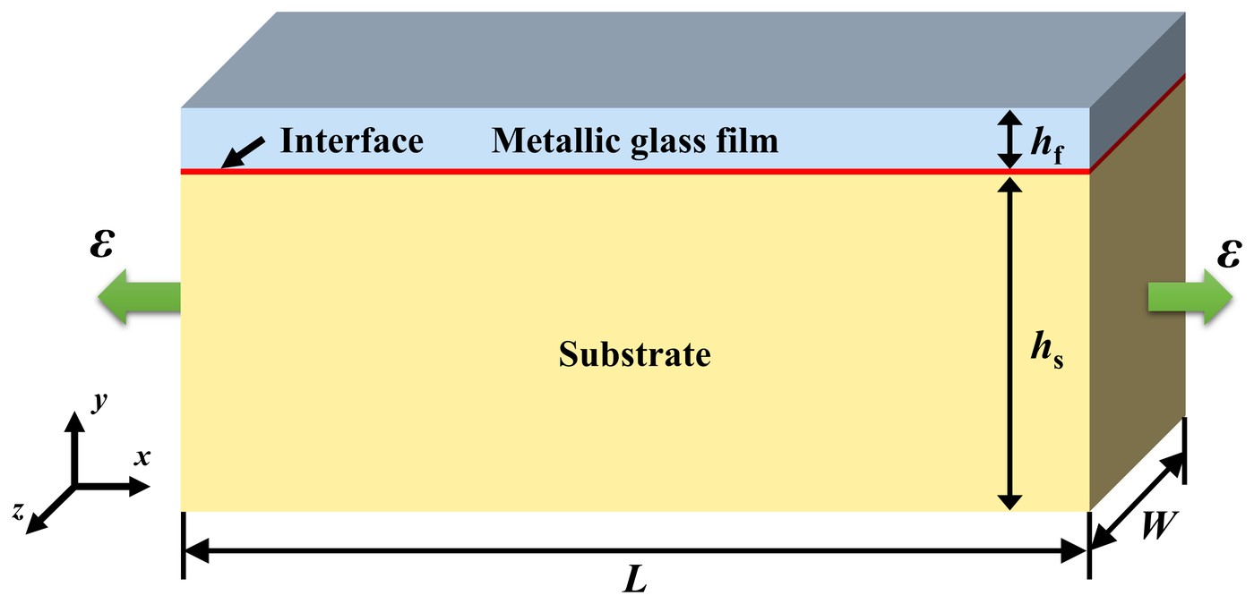
The model is a metallic glass film on a substrate, stretched along its length. The film is 2.5 to 30 μm thick, the substrate 735 μm, and the model 200 μm long. Most results come from two-dimensional plane strain simulations in Abaqus; a three-dimensional model, 80 μm wide, is used to compare with experiments.
The film follows the free volume theory, which captures how shear bands form in a metallic glass and how it softens. Free volume measures how far the glass departs from an ideally ordered structure: shear creates it, and the glass flows faster where it has more. The theory runs in Abaqus as a user material, with a Young's modulus of 217 GPa, a Poisson's ratio of 0.37 and a measured yield strength of 2 GPa. A random initial free volume, with a mean of 0.05, gives the bands places to start.
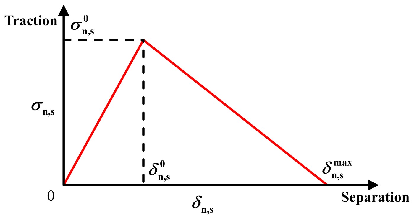
The interface is a cohesive zone. Its traction rises with separation until it reaches the interface strength, at 0.1 μm, and then falls to zero at 0.2 μm, when the interface has failed. The interface strength is varied from a tenth of the film's yield strength to five times it. The three-dimensional model is perfectly bonded instead, which the paper justifies by the small effect of the interface on films thicker than 10 μm.
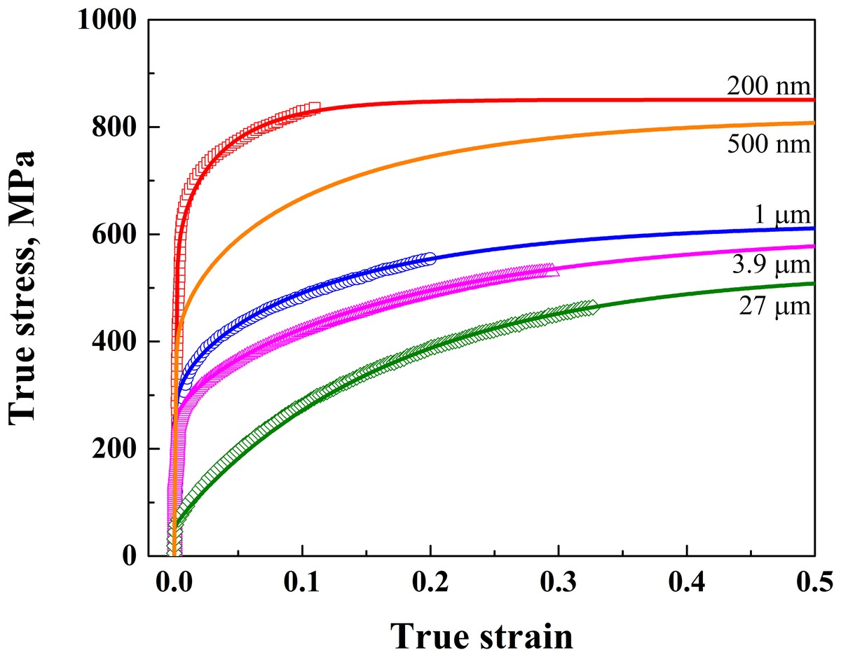
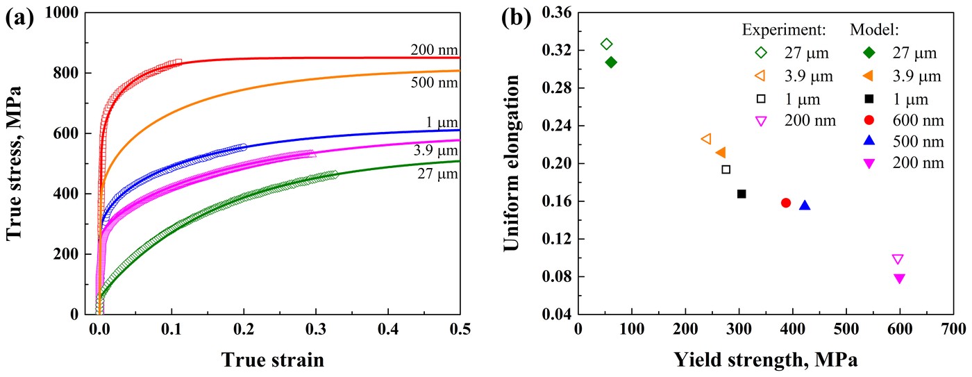
The Ni substrate follows a plasticity model based on dislocation density: a Kocks-Mecking model whose dynamic recovery depends on grain size. Fitted to measured stress-strain curves, it covers grains from 200 nm to 27 μm; unless stated otherwise, the substrate's grains are 3.9 μm. Polymer substrates, studied as well, are modeled as neo-Hookean solids.
2 Shear band multiplication #
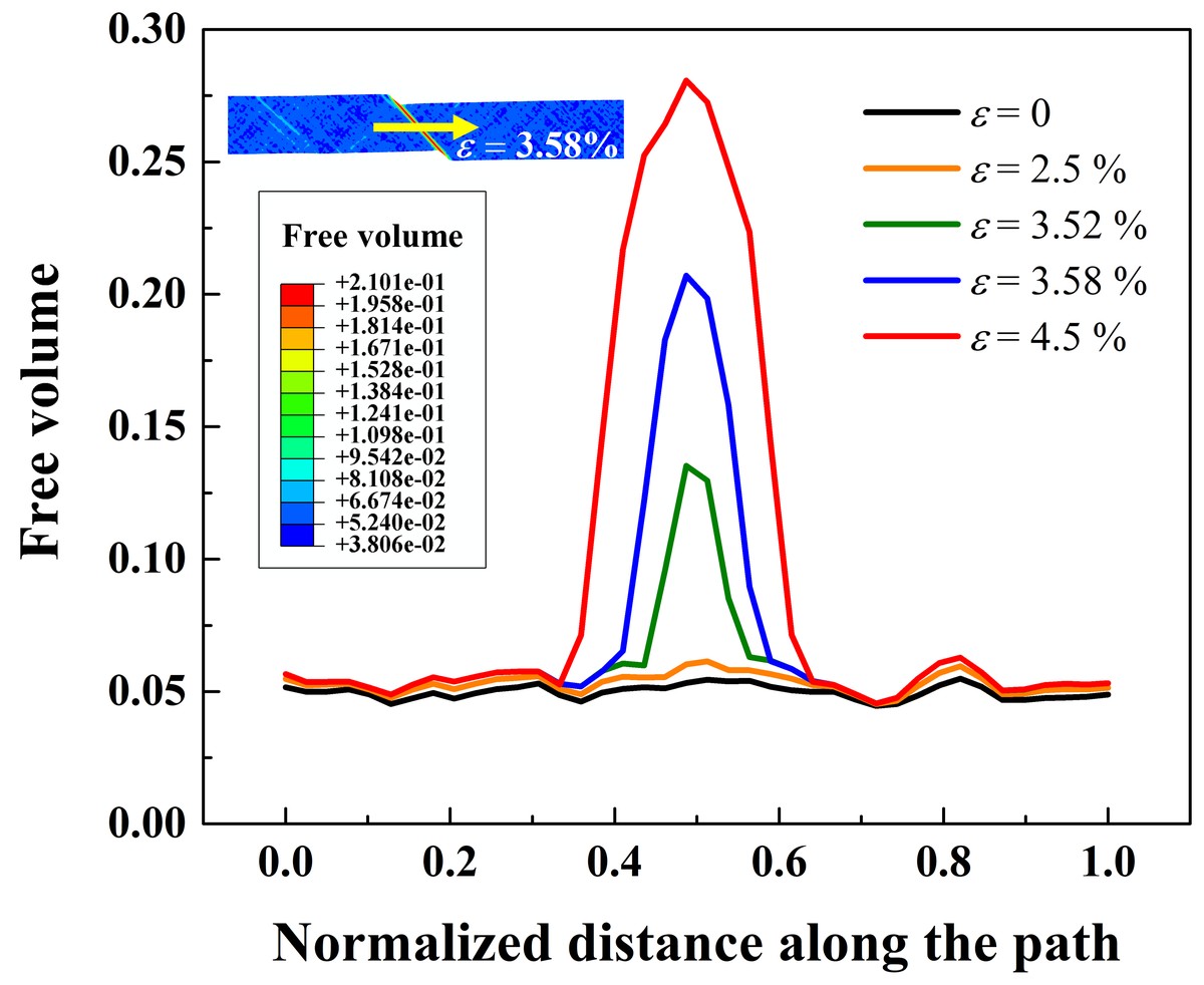
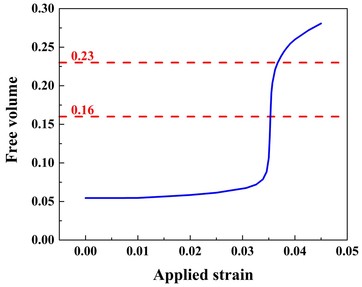
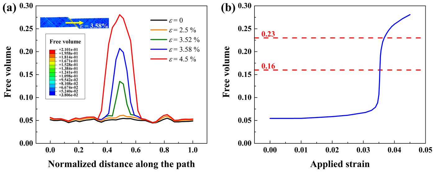
Free volume marks where shear bands form. Followed across the band in a freestanding 5 μm film, it hardly changes outside the band, while inside it rises slowly until the strain nears 3.5% and then jumps, from 0.079 at 3.4% strain to 0.221 at 3.62%. The paper takes a free volume of 0.16, within that jump, as the sign of a shear band, and 0.23 as fracture.
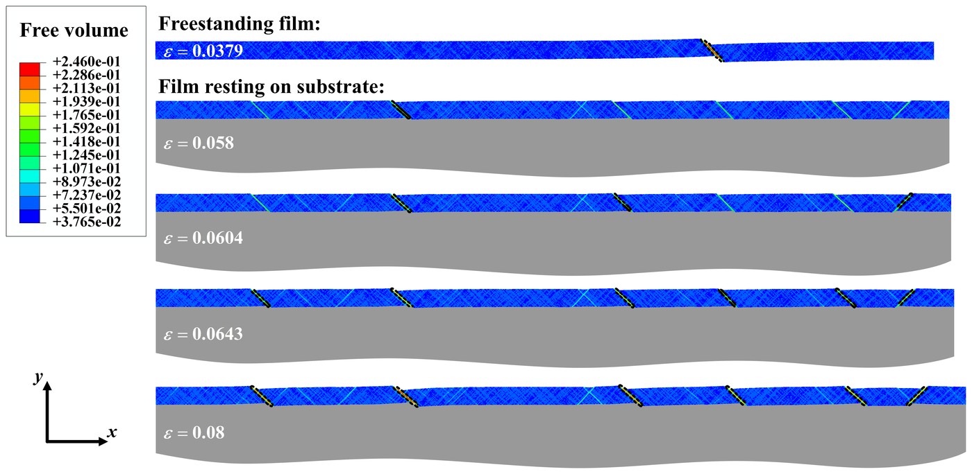
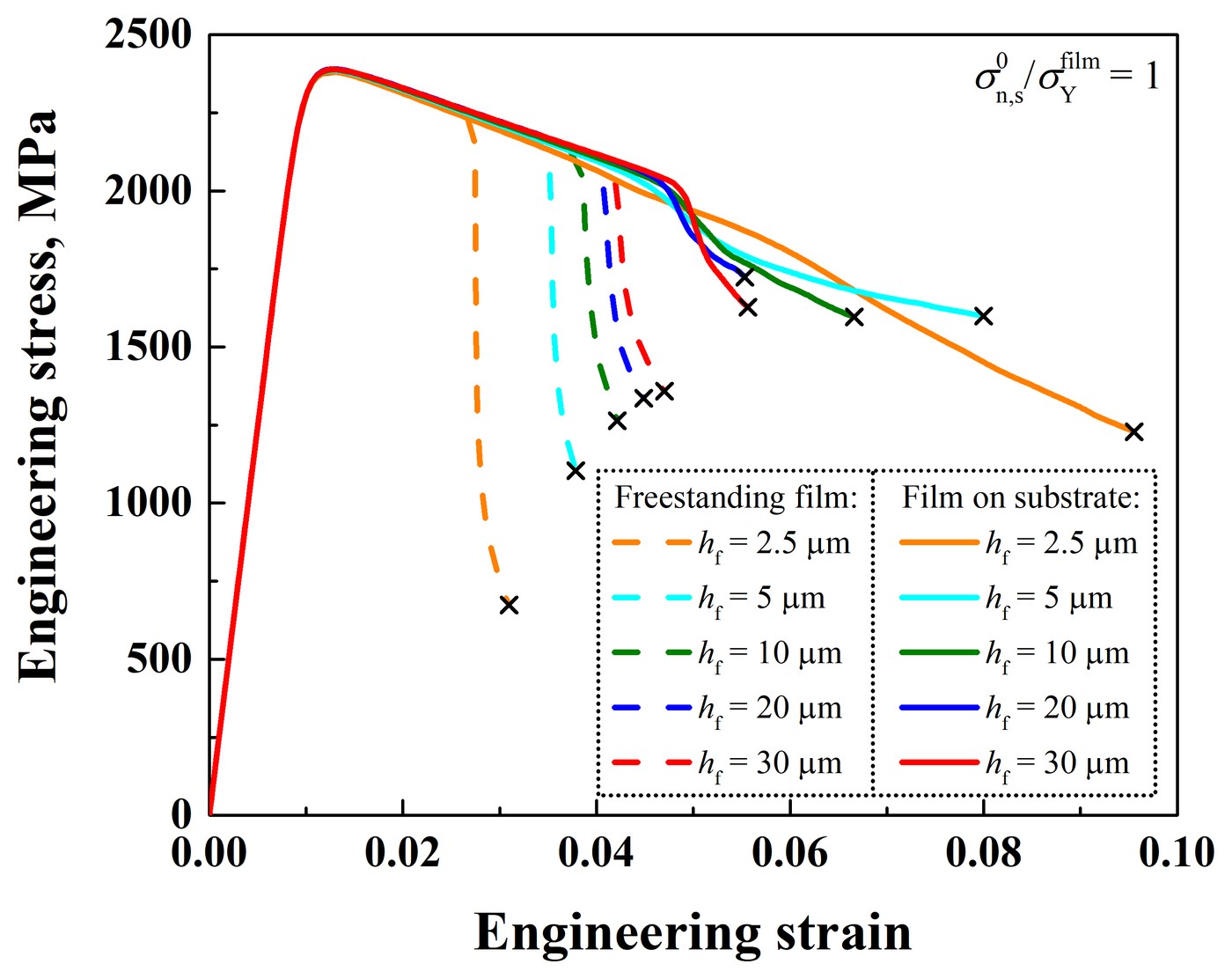
A freestanding 5 μm film forms a single shear band and fractures at 3.79% strain. On the substrate, the same film forms one band at 5.8%, six by 6.43%, and fractures at 8%, more than twice the strain. Multiple shear bands like these have been observed in experiments on such films.
Spread over several bands, the deformation no longer localizes. The simulations give the stress in the film itself, which is hard to measure in experiments. A freestanding film loses strength suddenly once its band forms; on the substrate, this drop is eased in a 30 μm film and gone in a 2.5 μm film, which fractures at 9.55% strain, over three times the 3.1% of the same film freestanding.
3 Film thickness and interface strength #
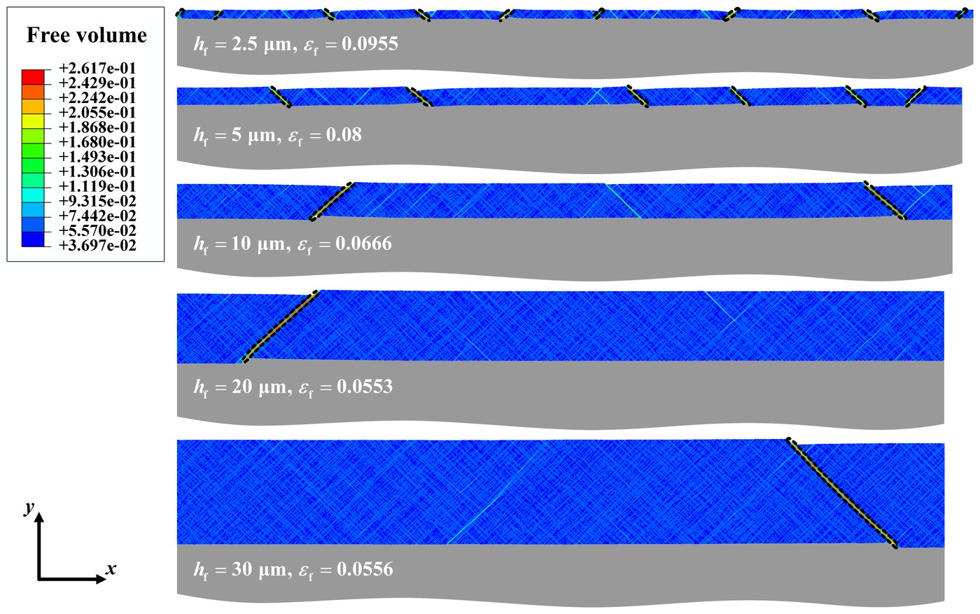
Thinner films gain the most. A 30 μm film on the substrate fractures at 5.56% strain, close to the 4.7% of the same film freestanding. The number of shear bands explains it: at fracture, a 2.5 μm film has nine bands, a 10 μm film two, and films 20 μm thick or more only one. In films thinner than 20 μm, new bands keep forming as the strain grows; the 2.5 μm film has five at 6.25% strain and nine at 9.55%.
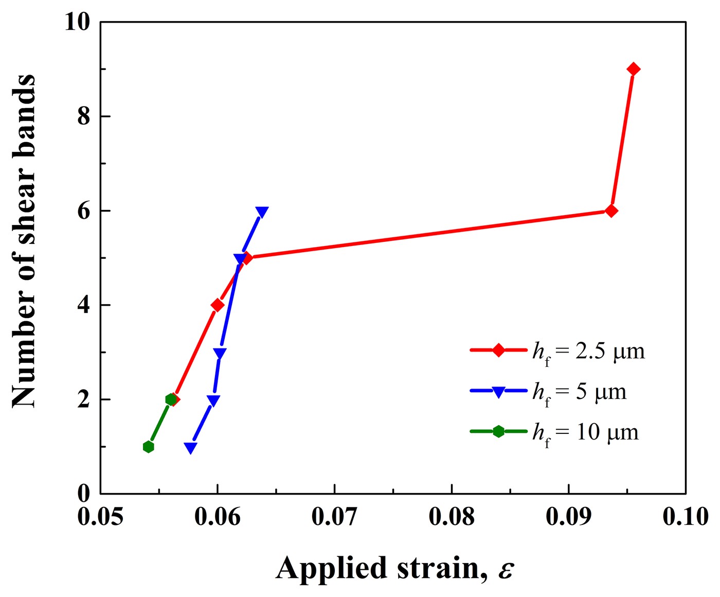
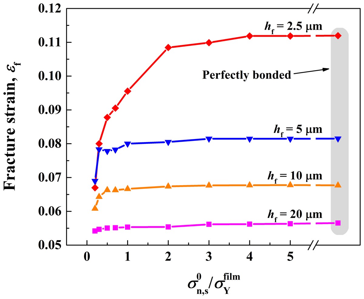
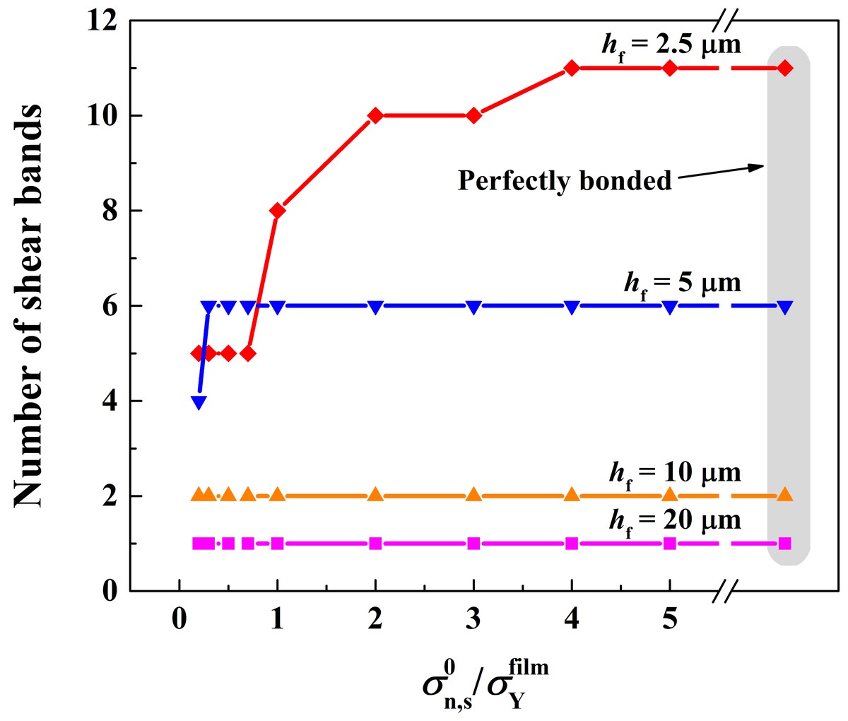
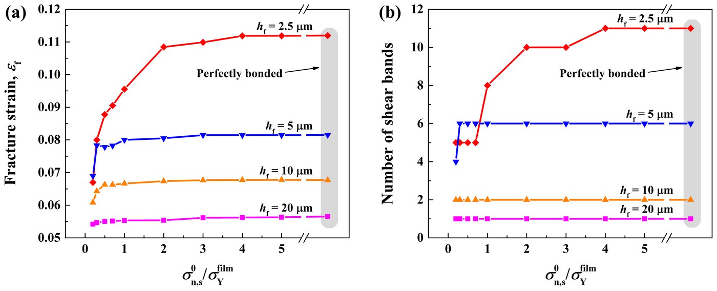
The interface has to hold the film down. When it is weak, the film delaminates from the substrate and fewer bands form: a 5 μm film forms two when the interface strength is a tenth of the film's yield strength. From half the yield strength up, it forms six bands and fractures at about 8% strain, as with a perfectly bonded interface.
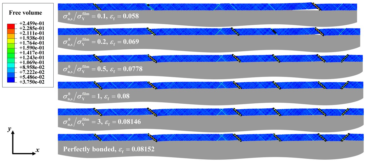
In thin films, the fracture strain and the number of bands both rise with the interface strength and then level off above a critical strength: about twice the film's yield strength for a 2.5 μm film, and half of it for a 10 μm film. In thicker films the interface hardly matters: a 20 μm film forms one band whatever its strength, and fractures at about 5.5% strain.
4 Substrate grain size, thickness and stiffness #
The substrate's grain size changes how much it helps. Among Ni substrates with grains from 200 nm to 27 μm, 500 nm grains give the most ductile film: a 2.5 μm film fractures at 13.3% strain, 50% more than on 27 μm grains, and forms 16 shear bands, against 7 on 27 μm grains.
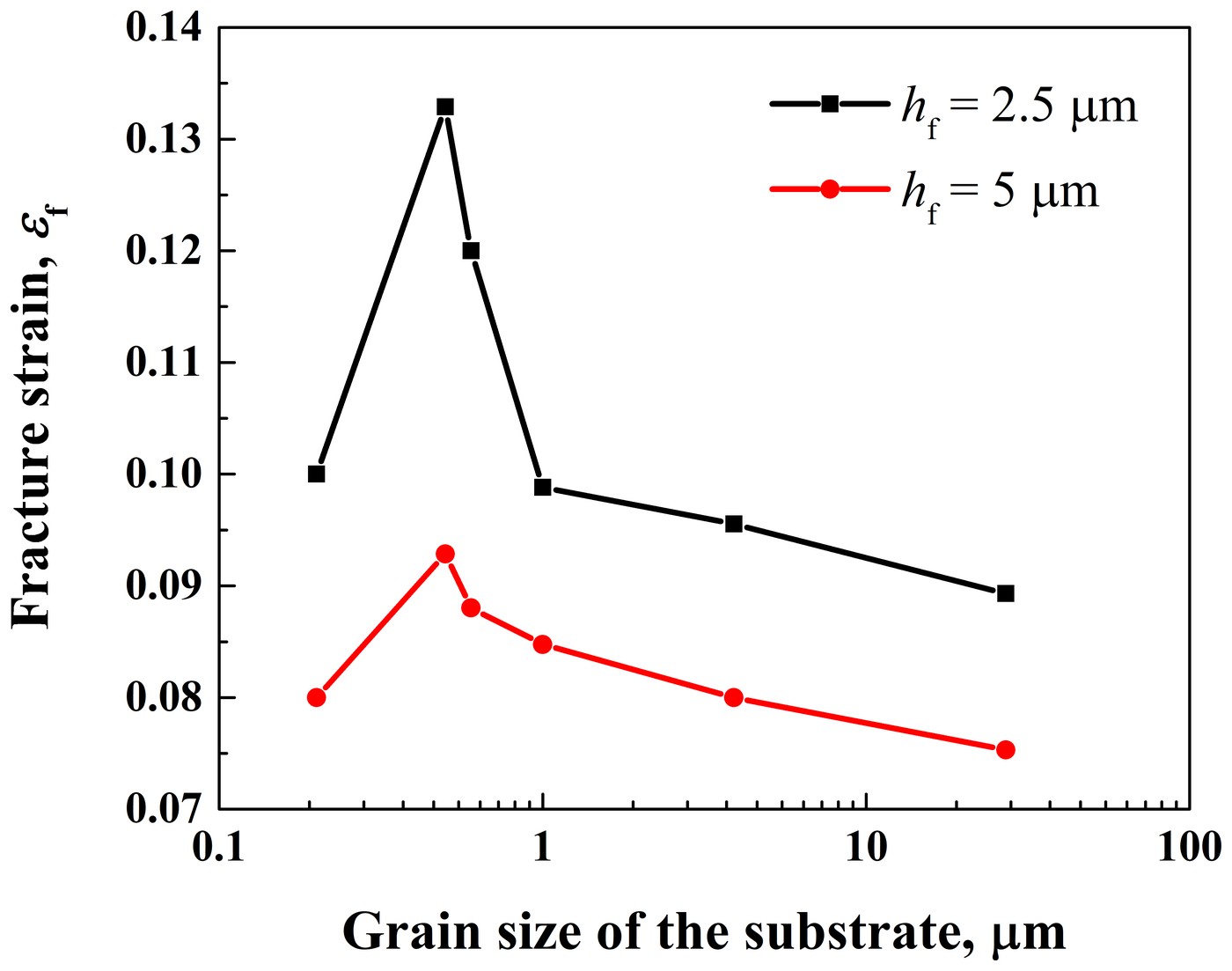
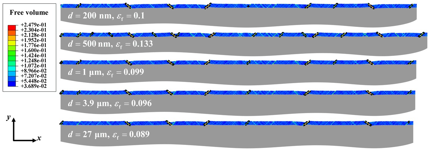
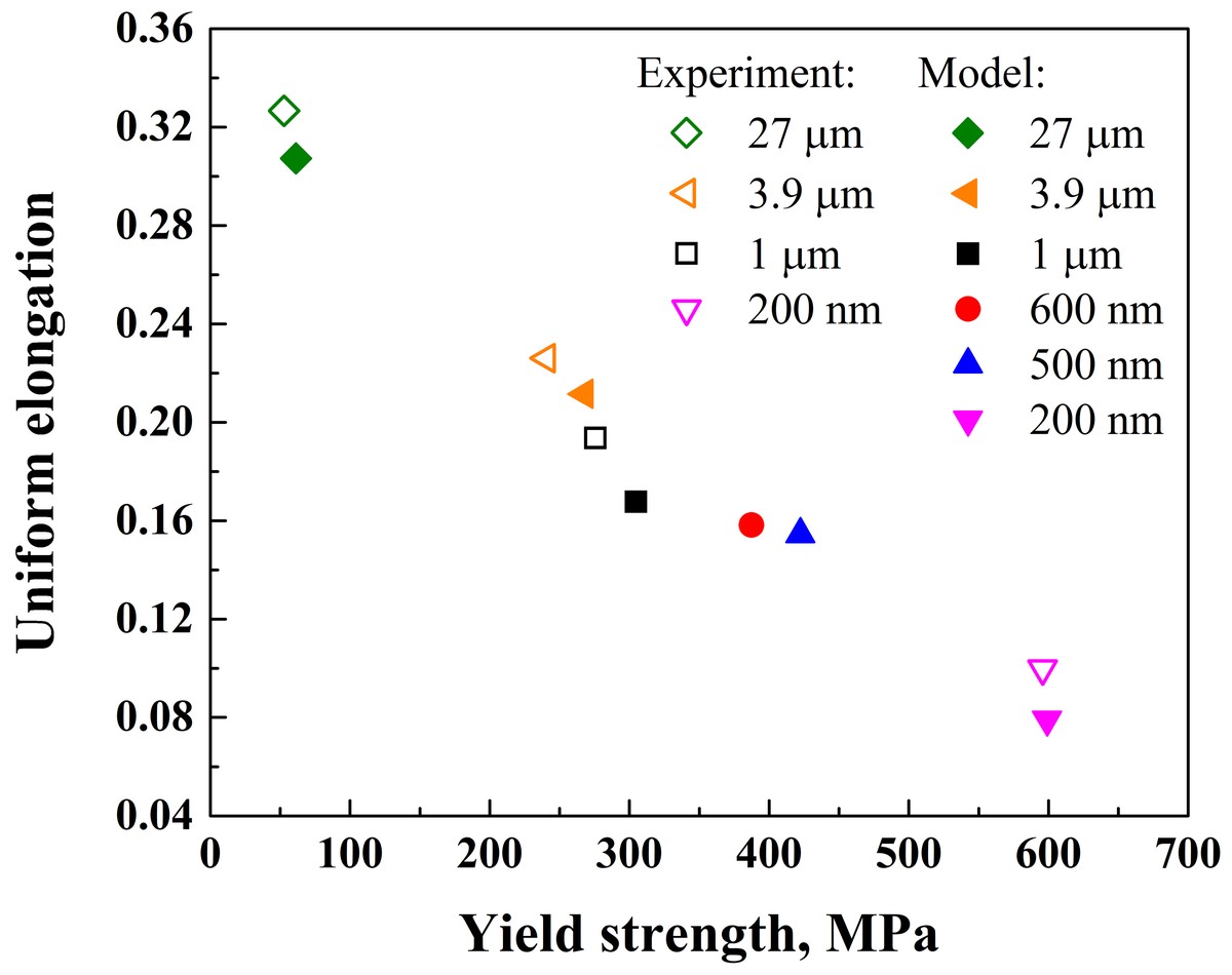
The optimum comes from the substrate's own trade-off between strength and ductility. Coarse grains make it weak: at 27 μm, its yield strength of 61.45 MPa is 1.9 GPa below the film's 2 GPa. Fine grains make it strong, but it then hardens less and stretches less: its uniform elongation at 200 nm is 0.079, about a quarter of the 0.31 at 27 μm. Both weaken the substrate's support for multiple shear bands, and 500 nm grains give the best balance.
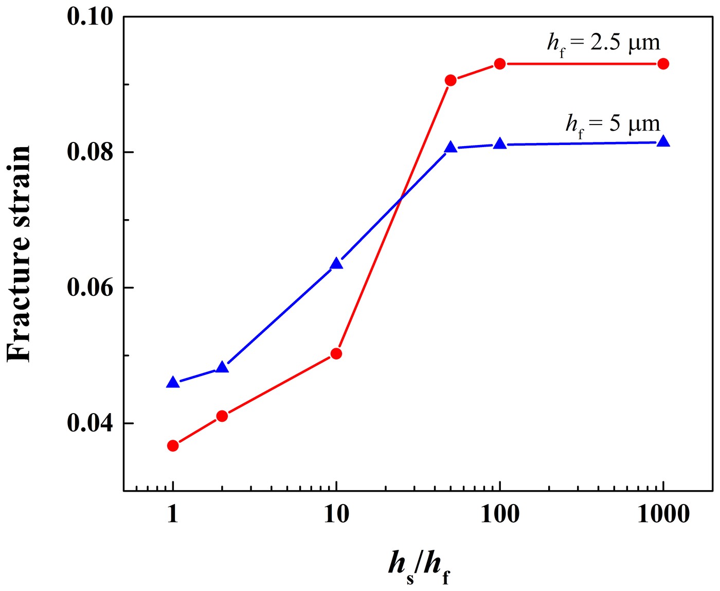
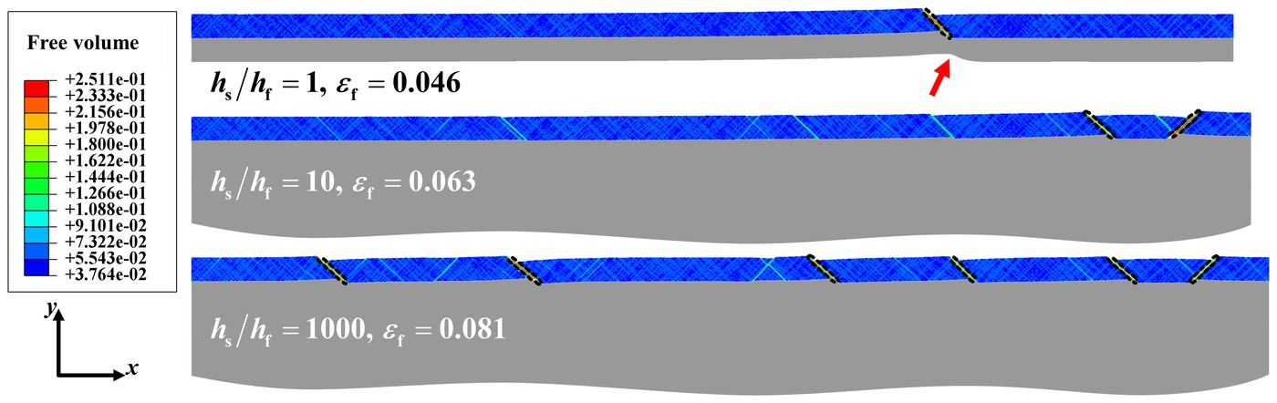
The substrate must also be thick enough. In these simulations the bottom of the model is left free. A substrate as thick as the film barely restrains it: a single band forms and runs on across the thin substrate, and a 2.5 μm film fractures at 3.7% strain, close to the 3.1% of a freestanding film. The fracture strain rises with the substrate's thickness and levels off once the substrate is about 50 times as thick as the film. For a 5 μm film, the number of bands grows from two to six as the substrate goes from 10 to 1000 times the film's thickness.
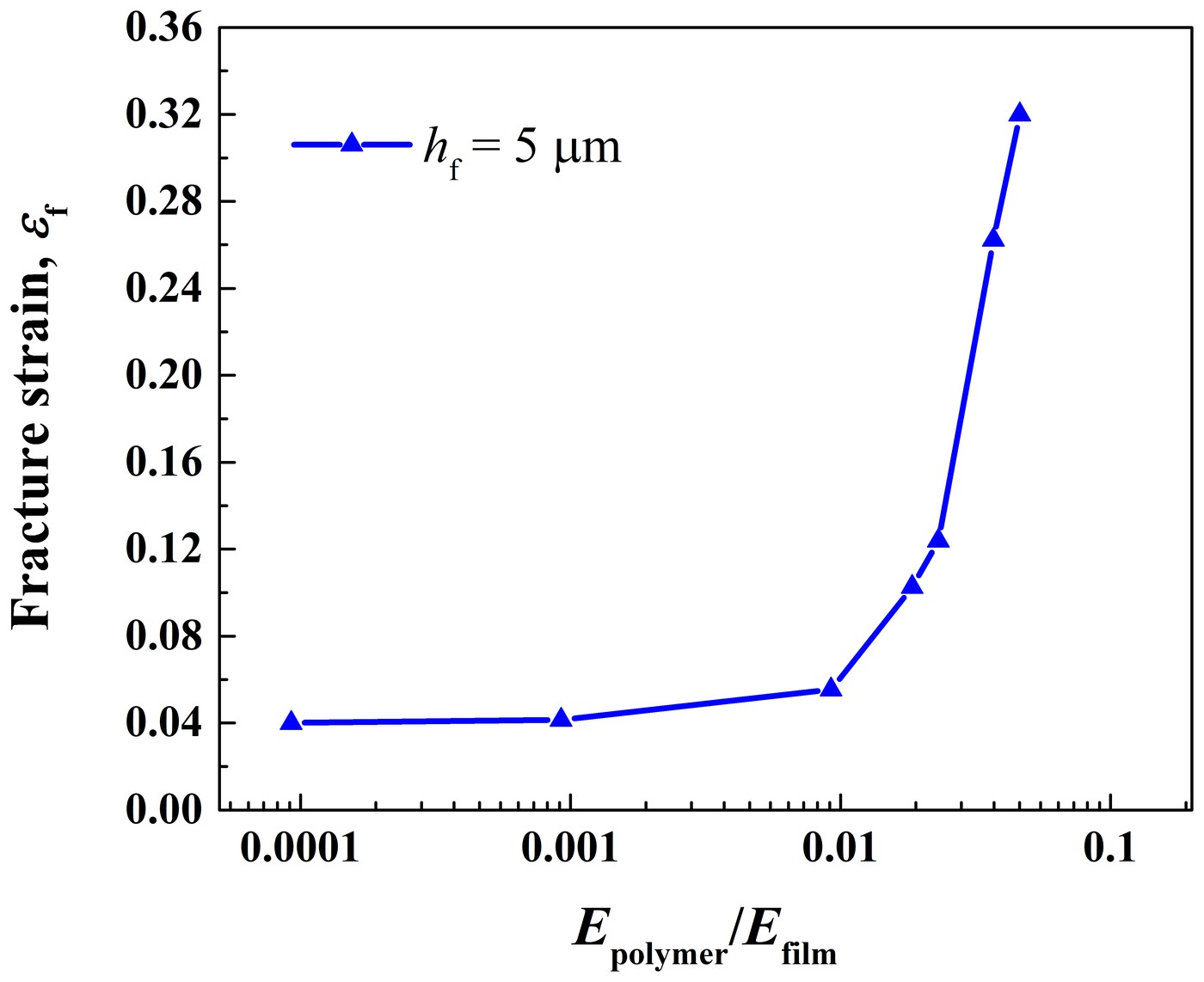
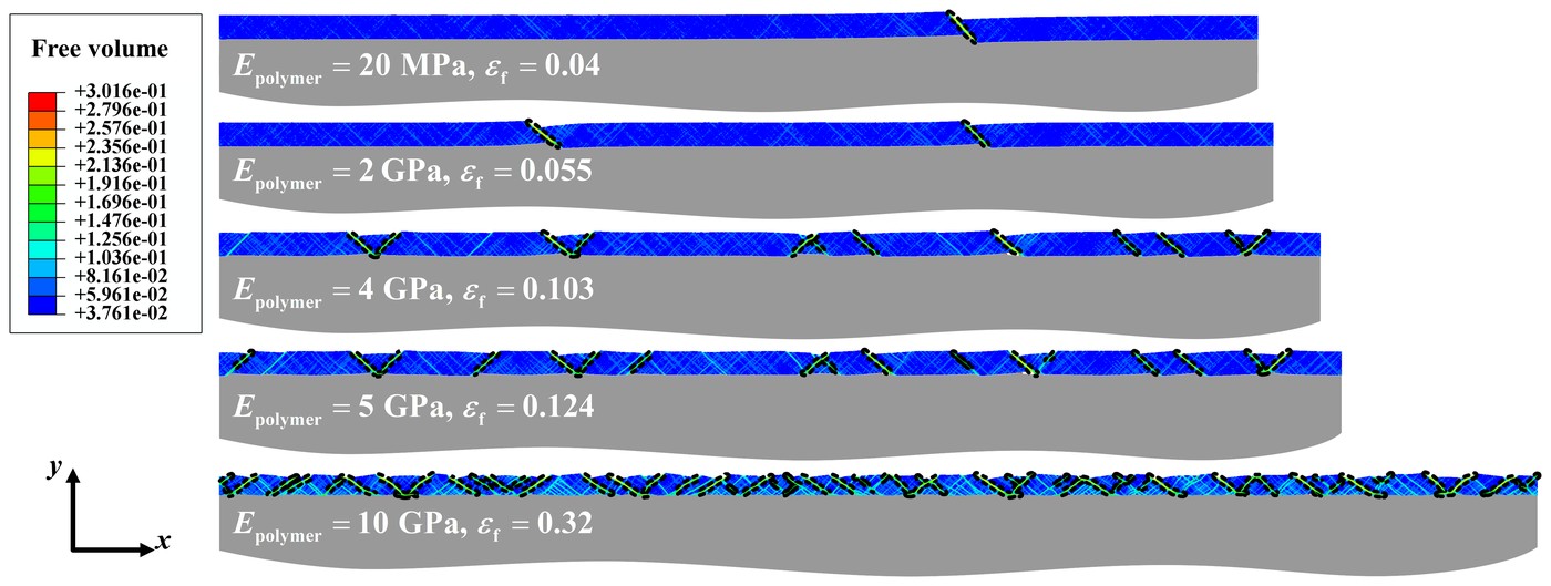
Polymer substrates help only if they are stiff enough. Modeled with moduli from 20 MPa to 10 GPa, they barely raise the fracture strain of a 5 μm film until the modulus passes a hundredth of the film's, 2.17 GPa; beyond that it rises steeply, to 32% strain at 10 GPa. A 20 MPa substrate carries only 0.82 MPa at 4% strain, far below the film's 2 GPa strength, so the film forms a single band and fractures at 4%, as a freestanding film does at 3.8%. At 10 GPa, dense shear bands spread along the whole film.
5 Comparison with experiments #
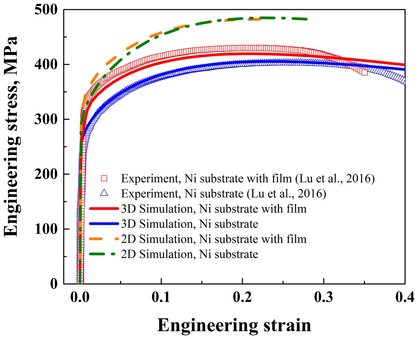
Lu et al. (2016) measured stress-strain curves of a 14.3 μm Ni-P film on a Ni substrate, and of the bare substrate. A three-dimensional model with that film thickness reproduces both. It predicts a tensile ductility of 21.18% for the film on its substrate and 23.17% for the bare substrate, against 21.82% and 25.36% measured, and it holds only until the specimens fracture. The two-dimensional model gives higher stresses, because plane strain adds a tensile stress across the width.
At the uniform elongation, 21.2%, the film in the three-dimensional model has four shear bands. They run at 45° to the tensile axis and straight through the film's thickness. The free volume peaks at the film's edge, so a crack would form there first, as seen in the experiments.
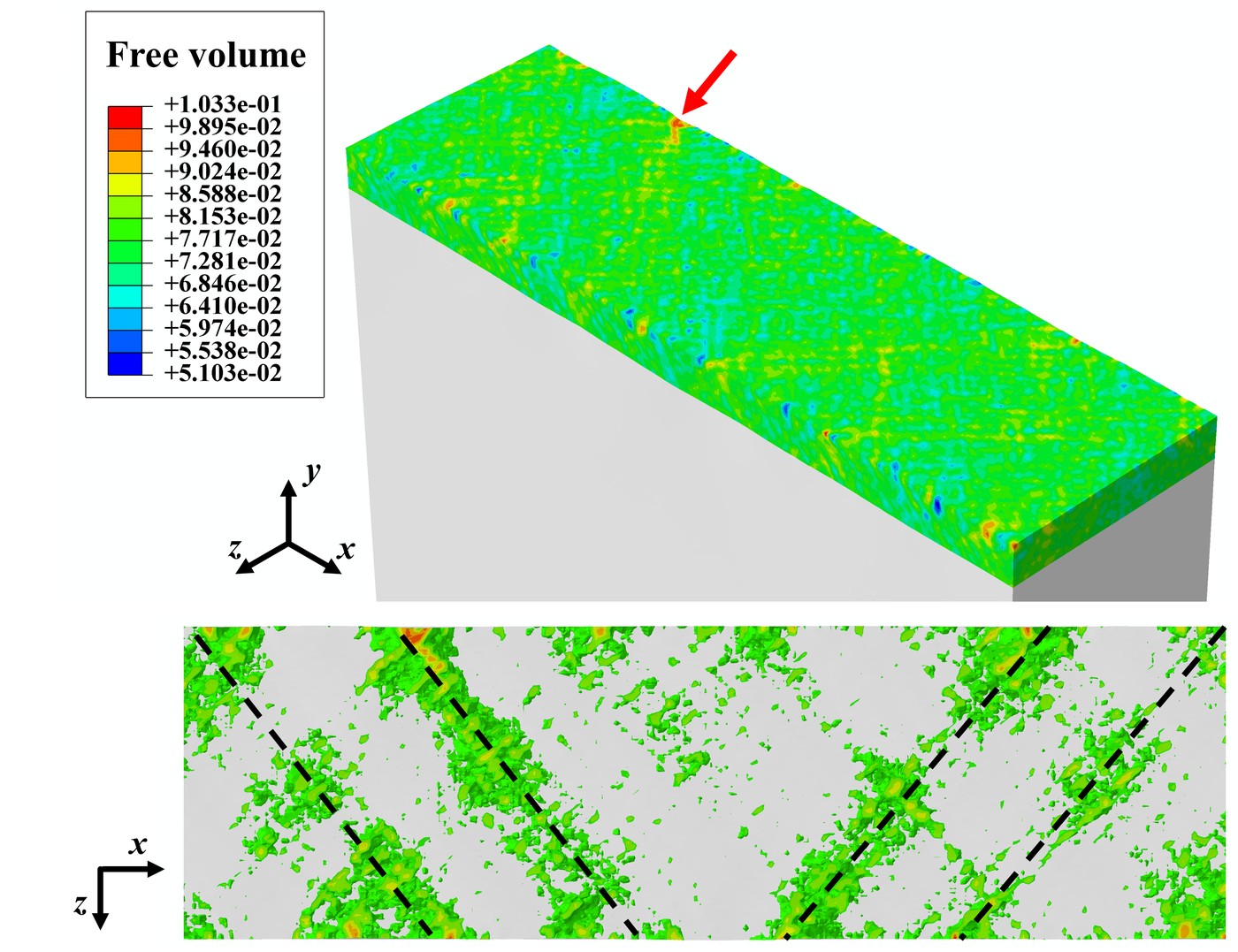
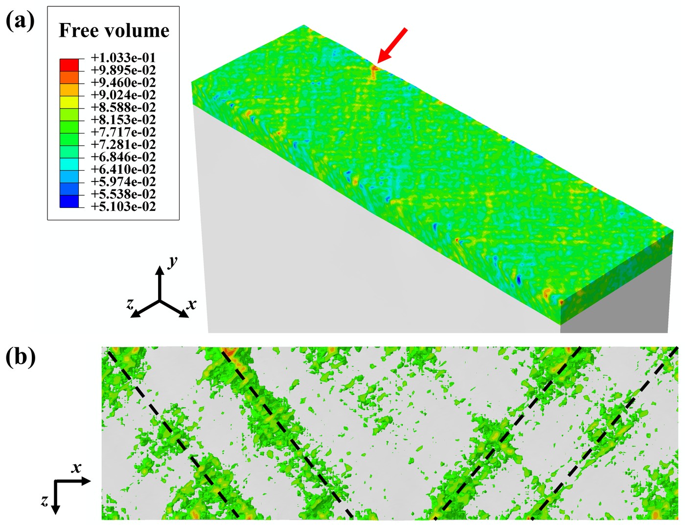
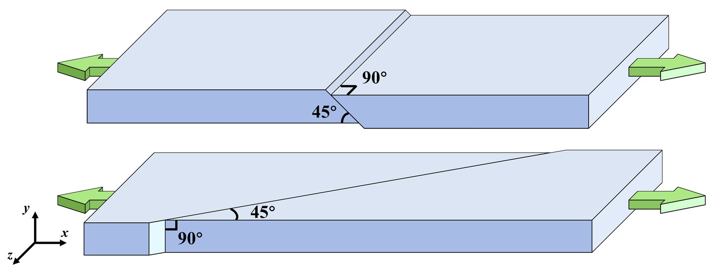
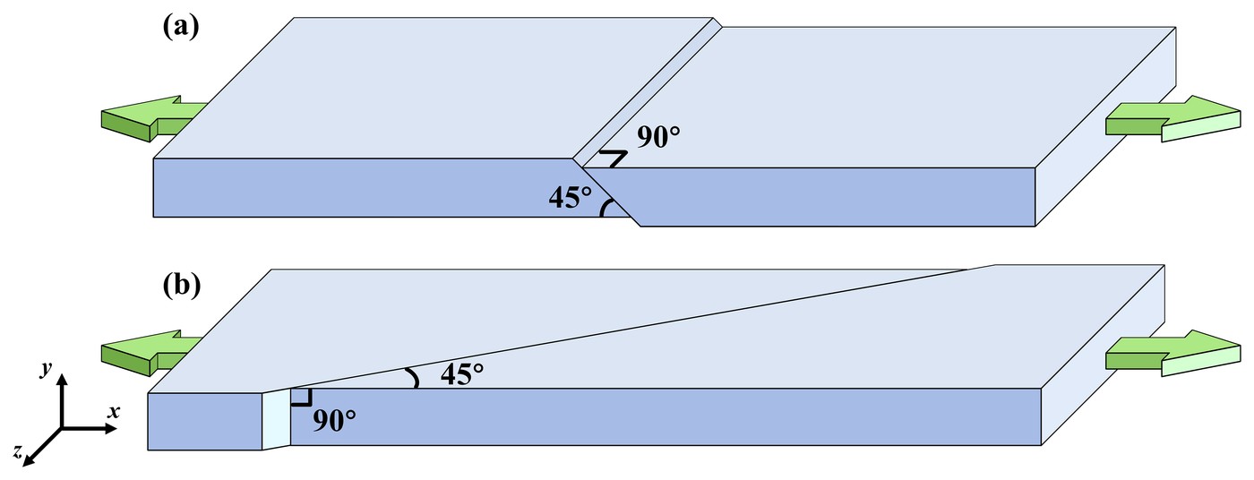
In the two-dimensional models, the bands run at 45° through the film's thickness instead. Plane strain adds a tensile stress across the width, which changes the direction of the largest shear stress, where bands form. Experiments show bands in both directions.
BibTeX #
@article{chen2020shear,
  title = {Shear band multiplication induced strong strain delocalization and high tensile ductility in amorphous thin films by metallic substrates},
  author = {Chen, Tianyu and Li, Jianjun and Chen, Shaohua and Li, Chun},
  journal = {International Journal of Solids and Structures},
  volume = {195},
  pages = {1--12},
  year = {2020},
  doi = {10.1016/j.ijsolstr.2020.03.011}
}