Tianyu Chen Programmable morphing structure with variable stiffness

Design and modeling of a programmable morphing structure with variable stiffness capability

Tianyu Chen, Xudong Yang, Yifan Wang*

School of Mechanical and Aerospace Engineering, Nanyang Technological University, Singapore

*Corresponding author: yifan.wang@ntu.edu.sg

International Journal of Mechanical Sciences 284, 109699 (2024)

A flat sheet whose hinges are scaled structures folds into a box within one second when the air is pumped out (real time).

Summary

Robots and deployable structures often need to change shape and then hold that shape under load. Adding a separate stiffening mechanism to a morphing structure makes it bulky, harder to control, and can stop it from reaching its target shape. This paper studies a scaled structure that does both with one mechanism, and turns it into a design method: rules for choosing its geometry, finite element simulations of what sets its shape and stiffness, and three devices built with it.

1 Working principle #

The structure has two layers with triangular teeth: a base layer, and a row of scales hinged to it. Both sit in a thin latex bag. With no pressure applied, the layers slide freely and the strip is soft enough to lie flat or sag.

Pumping the air out of the bag presses the scales onto the base layer. The scales' teeth are spaced wider than the base layer's, so they mesh only when the strip bends: it curls until every tooth sits flush, which happens at the curvature the teeth were cut for. Pressed together, the two layers then work as one thicker plate, so the strip is also stiff.
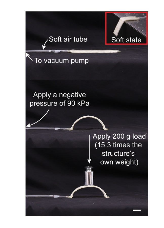
IllustrationA strip with one tooth per scale curls into a half circle and then carries a load. The latex bag is not drawn.
The printed strip lying soft, curled into an arch under negative pressure, and holding a 200 g weight
The printed structure, soft at first, takes its arch at a negative pressure of 90 kPa and then holds 200 g, 15.3 times its own weight. Scale bar, 2 cm. Adapted from Chen et al., International Journal of Mechanical Sciences 284, 109699 (2024). Full figure

2 Design method #

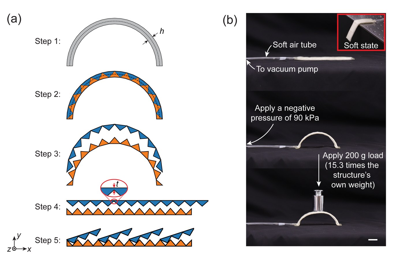
The design method, which the paper calls layered tessellation, starts from the target shape. The curve is drawn with the structure's thickness and filled with alternating triangles. The triangles are split into two layers, each layer is straightened by turning its triangles, a thin layer is added to its back to join them, and the upper layer is cut into scales.
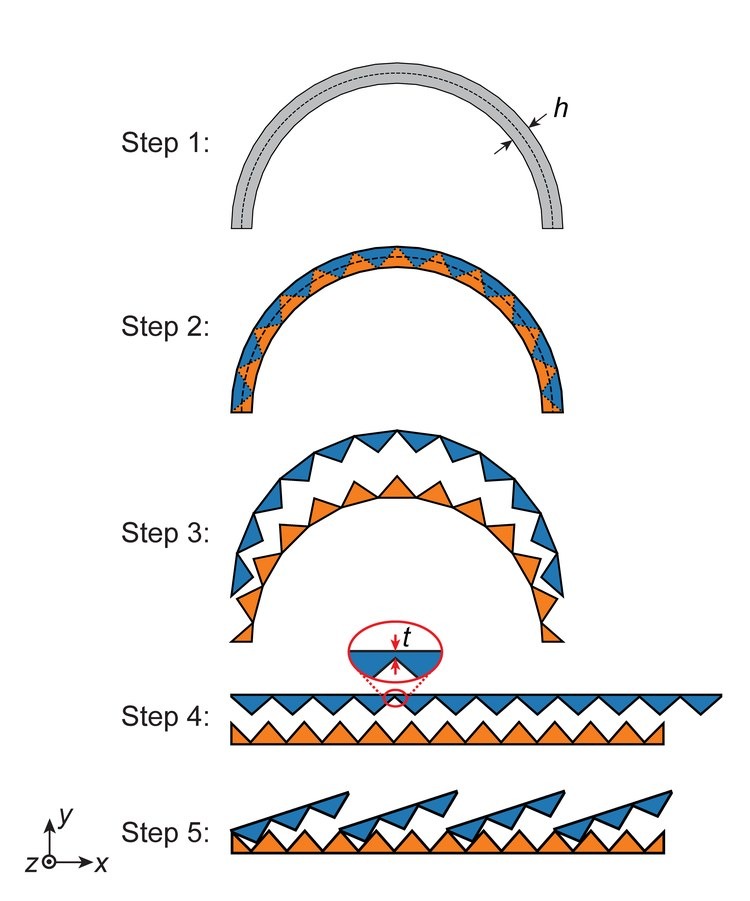
Five steps from a half-circle target to a flat strip of scales on a base layer
The five steps for a half-circle target: the target, its triangles, the two layers apart, each layer straightened (inset: the thin layer of thickness t that joins its triangles), and the upper layer cut into scales. Adapted from Chen et al., International Journal of Mechanical Sciences 284, 109699 (2024). Full figure

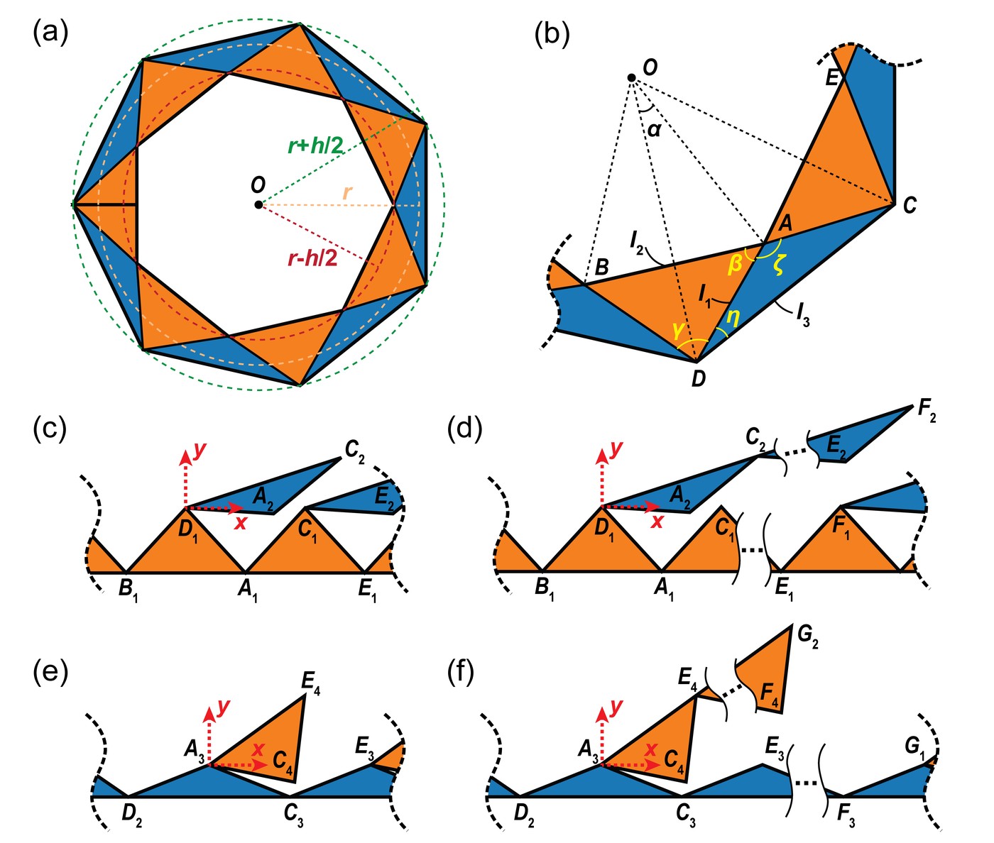
Four independent parameters define a structure: the target radius r, the thickness h, the number of scales ns and the number of periods on each scale np. From the geometry of one period, the paper derives the conditions under which the scales still mesh with the base layer when the strip lies flat.
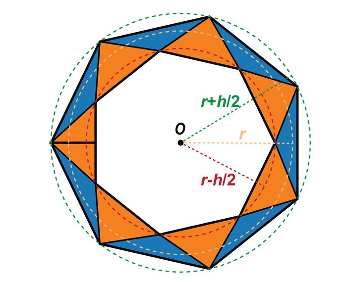
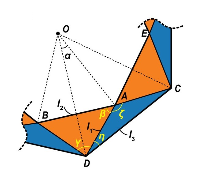
A circular target filled with alternating triangles, with its radius and thickness marked One period of the circle, with the lengths and angles used in the design conditions
Left, a circular target of radius r and thickness h, filled with triangles. Right, one period, with the lengths and angles used in the design conditions. Adapted from Chen et al., International Journal of Mechanical Sciences 284, 109699 (2024). Full figure
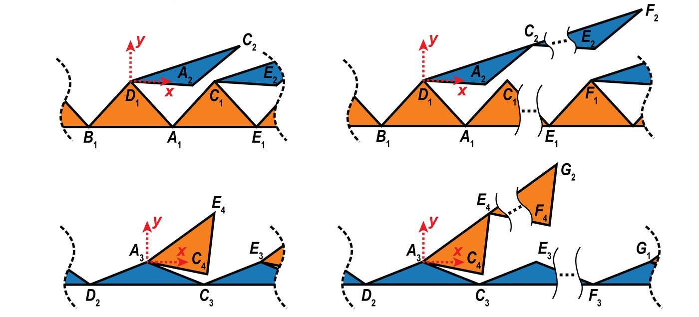
Scales lying on a flat base layer, with one or several periods per scale, for either choice of base layer
Laid flat, each scale must still fit the base layer beneath it. Top, with the smaller triangles as the base layer, for one period per scale and for several; bottom, with the larger triangles as the base layer. Adapted from Chen et al., International Journal of Mechanical Sciences 284, 109699 (2024). Full figure

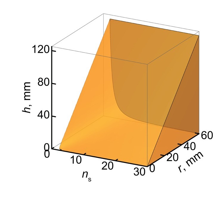
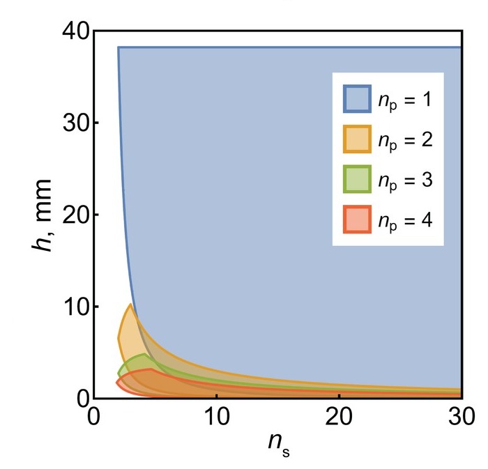
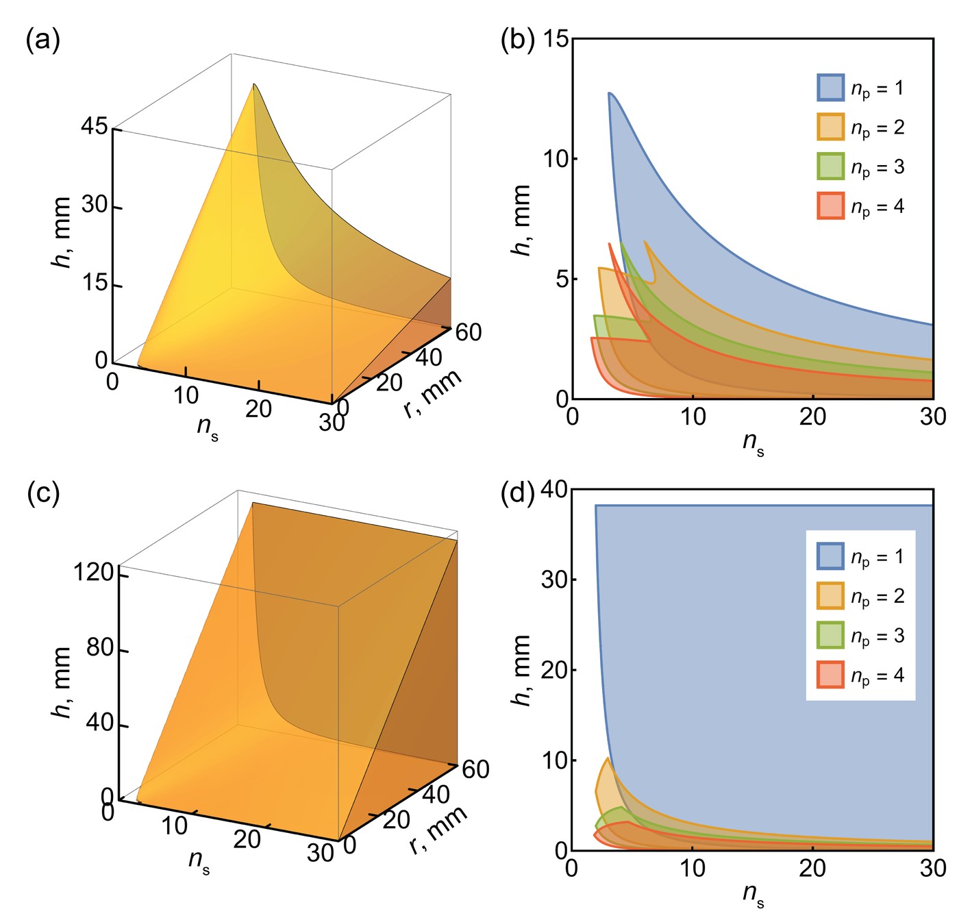
Those conditions bound the design. With the smaller triangles as the base layer and one period per scale, the thickest possible structure grows with the target radius and falls quickly as scales are added, and more periods per scale narrow the range further. Using the larger triangles as the base layer triples it, up to 120 mm thick at a 60 mm radius, but it too shrinks quickly once a scale carries more than one period.
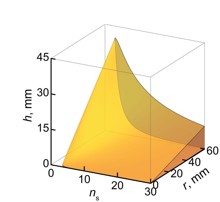
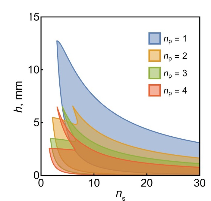
Allowed thickness against the number of scales and the radius, smaller triangles as the base layer Allowed thickness against the number of scales for one to four periods, smaller triangles as the base layer Allowed thickness against the number of scales and the radius, larger triangles as the base layer Allowed thickness against the number of scales for one to four periods, larger triangles as the base layer
The allowed thickness h. Top, with the smaller triangles as the base layer: against the number of scales and the target radius with one period per scale, and against the number of scales with one to four periods per scale at r = 19.1 mm. Bottom, the same with the larger triangles as the base layer. Adapted from Chen et al., International Journal of Mechanical Sciences 284, 109699 (2024). Full figure
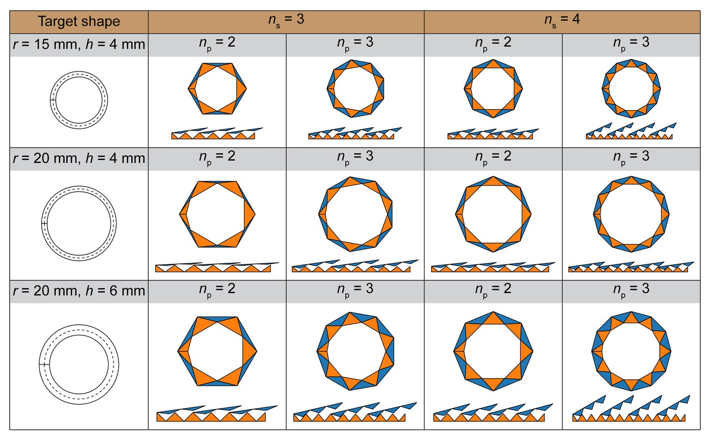
A table of three targets, each flattened with three or four scales of two or three periods
The four parameters are independent: three targets, each flattened with three or four scales of two or three periods. From Chen et al., International Journal of Mechanical Sciences 284, 109699 (2024).

3 Finite element model #

Two-dimensional plane strain models in Abaqus/Explicit include the scales, the base layer, the latex bag and the test fixtures. The printed TPU is modeled as elastic with a measured modulus of 55.7 MPa, the latex as a neo-Hookean solid, and the friction between each pair of materials comes from inclined plane tests.
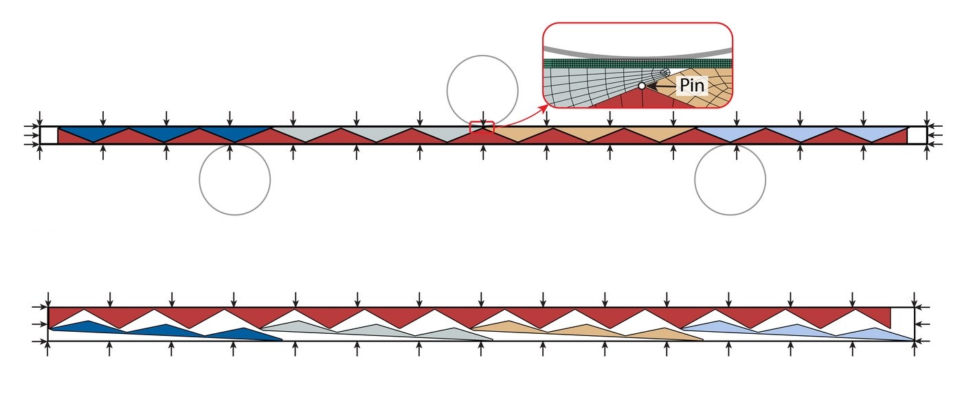
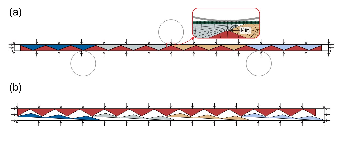
The finite element models of the bending test and of morphing
The models for the three-point bending test (top) and for morphing (bottom); the inset shows the pin connection between a scale and the base layer. Adapted from Chen et al., International Journal of Mechanical Sciences 284, 109699 (2024). Full figure

The models match three-point bending tests at negative pressures from 0 to 90 kPa, and they track how the curvature approaches its target as the pressure rises. The simulated final curvature is slightly higher than the measured one, which the paper attributes to the PTFE tape on the printed parts.
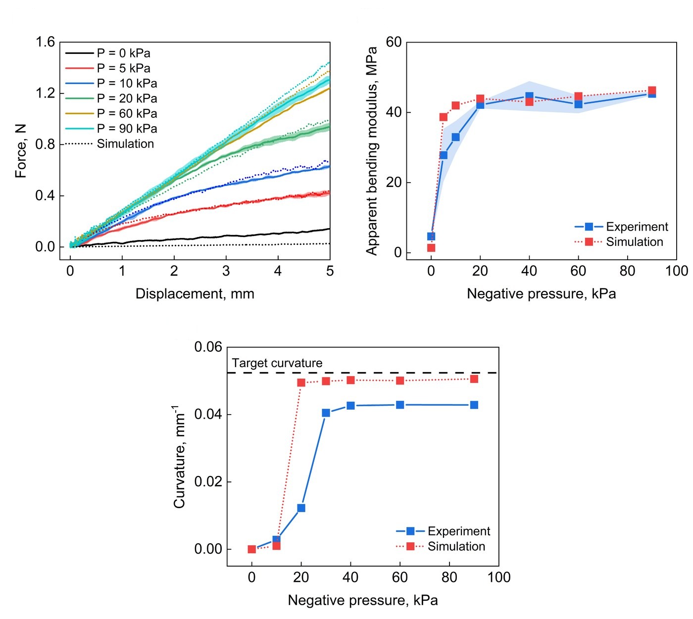
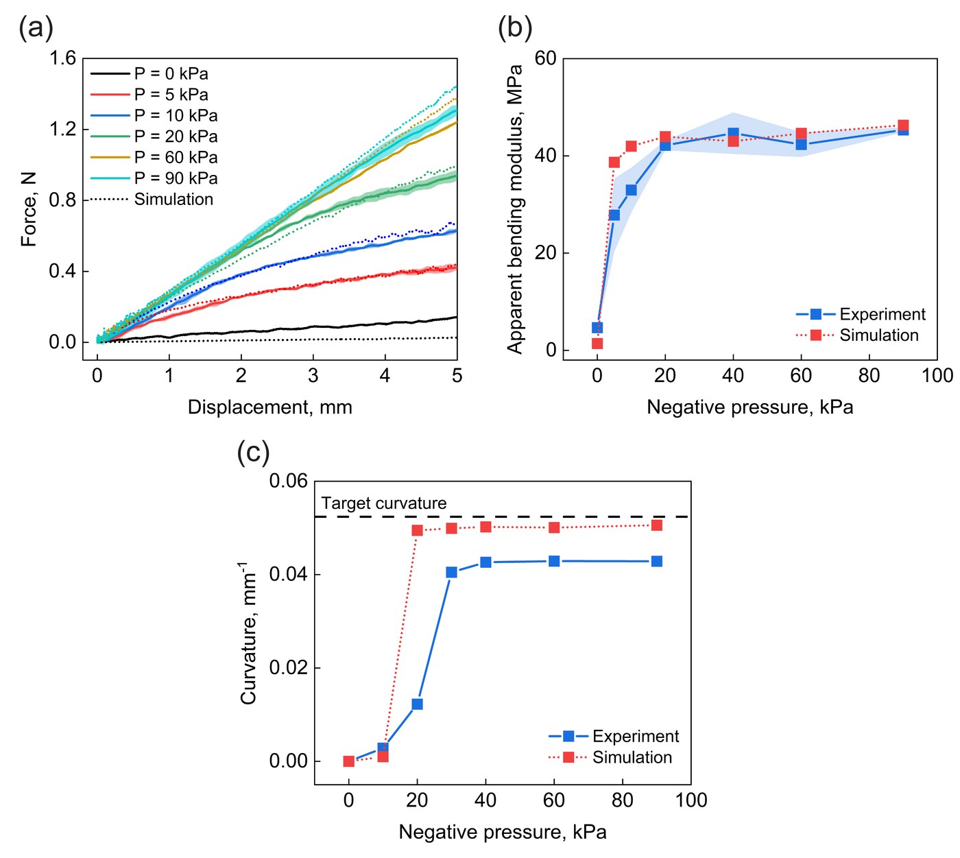
Measured and simulated force, bending modulus and curvature
Experiments against simulations: force against displacement in three-point bending at negative pressures from 0 to 90 kPa (top left), and the apparent bending modulus (top right) and the curvature (bottom) against the negative pressure. Adapted from Chen et al., International Journal of Mechanical Sciences 284, 109699 (2024). Full figure

4 Effects of friction, scales and tooth shape #

Friction between the scales and the base layer decides whether the structure can morph at all. A force analysis of one unit, with each period treated as a rigid body hinged at its vertices, gives the friction coefficient above which a scale can no longer slide on the base layer: the layers lock before the strip reaches its shape.
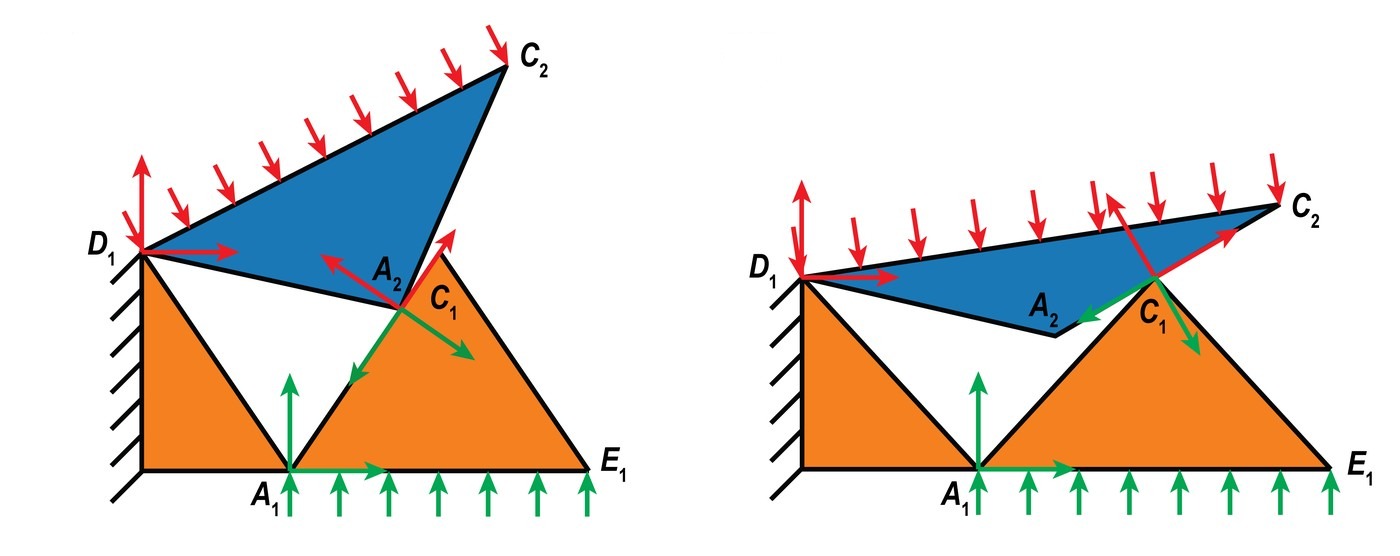
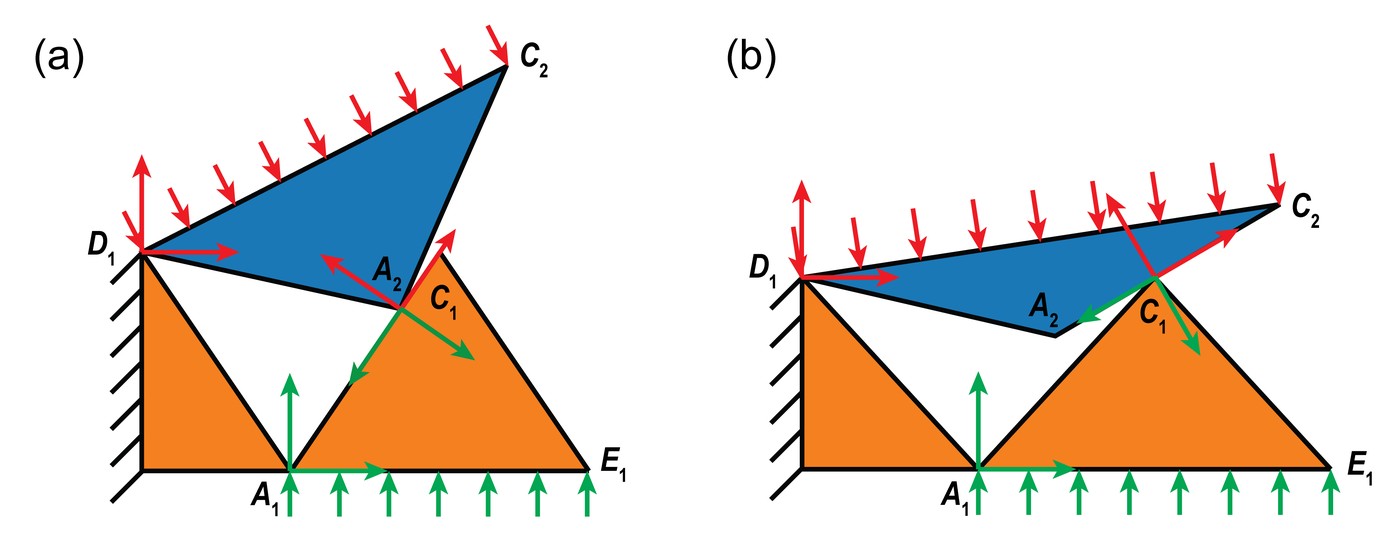
Forces on a scale and on the base layer in one unit, for two contact configurations
The forces on a scale (red) and on the base layer (green) in one unit, when the scale's tip touches the base layer's edge (left) and when the base layer's tip touches the scale's edge (right). Adapted from Chen et al., International Journal of Mechanical Sciences 284, 109699 (2024). Full figure
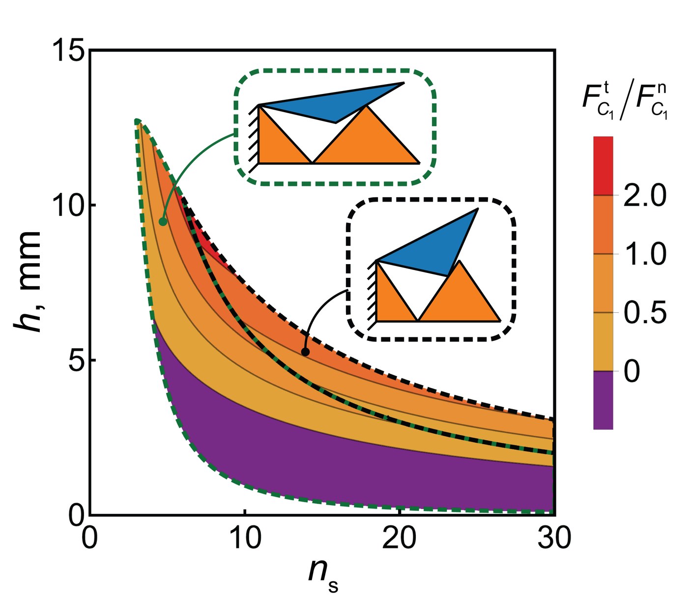
Map of the friction coefficient at which the layers lock, against thickness and number of scales
The friction coefficient above which the layers lock, against thickness and number of scales (r = 19.1 mm). In the purple region the strip would bend the wrong way; the insets show the unit in the two configurations. From Chen et al., International Journal of Mechanical Sciences 284, 109699 (2024).

Simulations of whole strips show the same kind of threshold. Their stiffness rises with friction, but above a critical coefficient, about 0.2 with four scales and 0.6 with eight, they no longer reach their target and may even bend the wrong way.
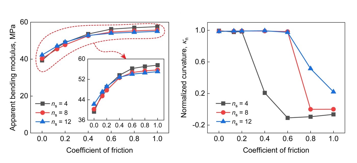
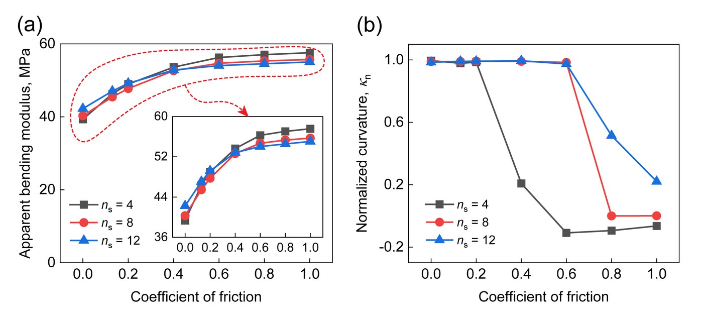
Bending modulus and normalized curvature against the friction coefficient
The apparent bending modulus (left) and the normalized curvature (right), which is 1 when the strip reaches its target, against the friction coefficient, for 4, 8 and 12 scales of three periods. Adapted from Chen et al., International Journal of Mechanical Sciences 284, 109699 (2024). Full figure

More periods per scale raise the stiffness but lower the curvature the strip reaches, a trade-off between morphing and stiffness.
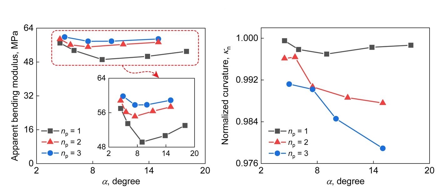
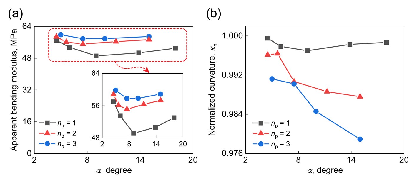
Bending modulus and normalized curvature against the central angle of one period
The apparent bending modulus (left) and the normalized curvature (right) against the central angle of one period, α, which shrinks as scales are added, for one to three periods per scale. Adapted from Chen et al., International Journal of Mechanical Sciences 284, 109699 (2024). Full figure

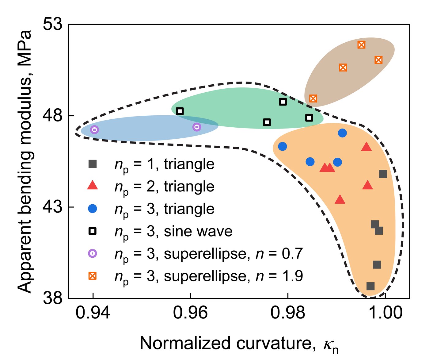
Changing the shape of the teeth overcomes the trade-off: with superellipse teeth of exponent 1.9, the structure reaches the highest stiffness and the highest curvature of the designs studied.
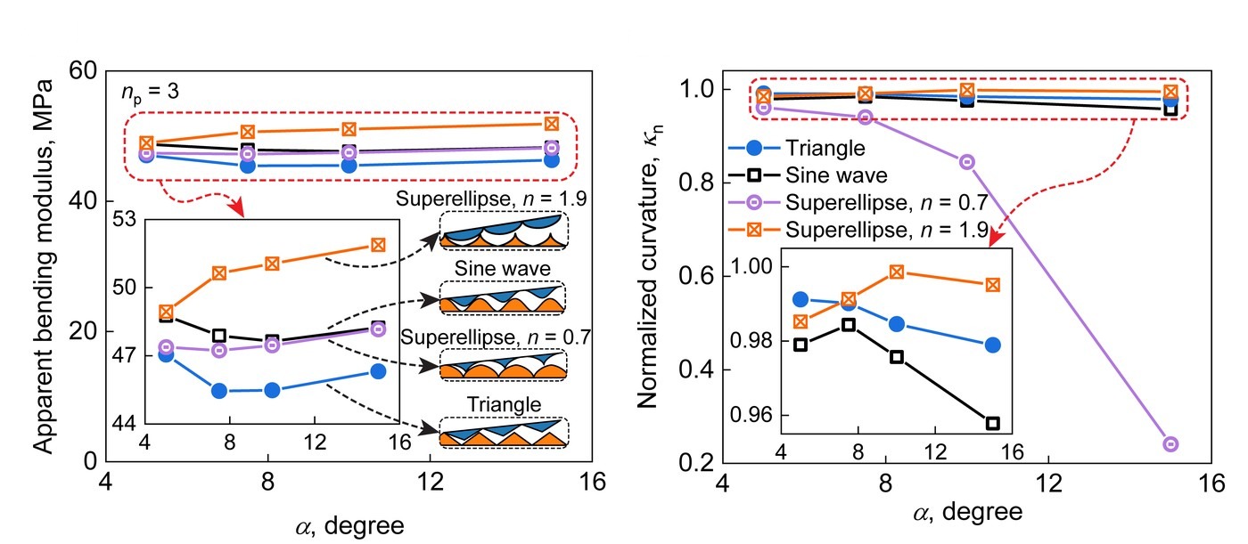
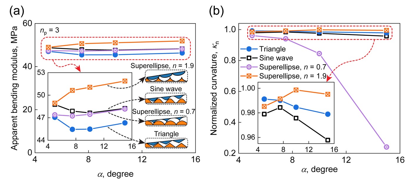
Bending modulus and normalized curvature for four tooth shapes
The same two measures for four tooth shapes, with three periods per scale: triangles, sine waves, and superellipses of exponents 0.7 and 1.9. Adapted from Chen et al., International Journal of Mechanical Sciences 284, 109699 (2024). Full figure
Apparent bending modulus against normalized curvature for all designs
Stiffness against how closely the strip reaches its target, for the tooth shapes and periods studied. From Chen et al., International Journal of Mechanical Sciences 284, 109699 (2024).

5 Demonstrations #

Printed from PLA for higher stiffness, the structure becomes a soft gripper, a phone stand and the hinges of a foldable box, all driven by a negative pressure of 90 kPa.

Each finger of the gripper is a strip designed for a quarter circle of radius 63.66 mm, 2 mm thick. Soft, the gripper folds flat; under pressure it opens out within 0.3 s, and it lifts a 147 g load, 7.35 times its own weight, not counting its frame.
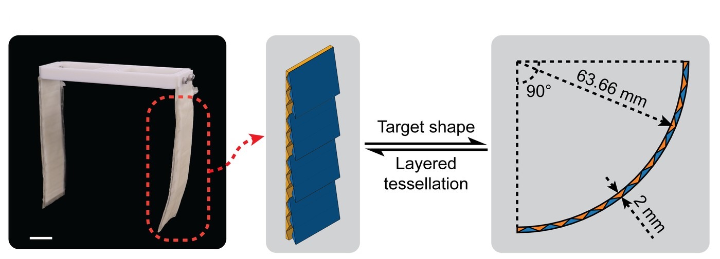
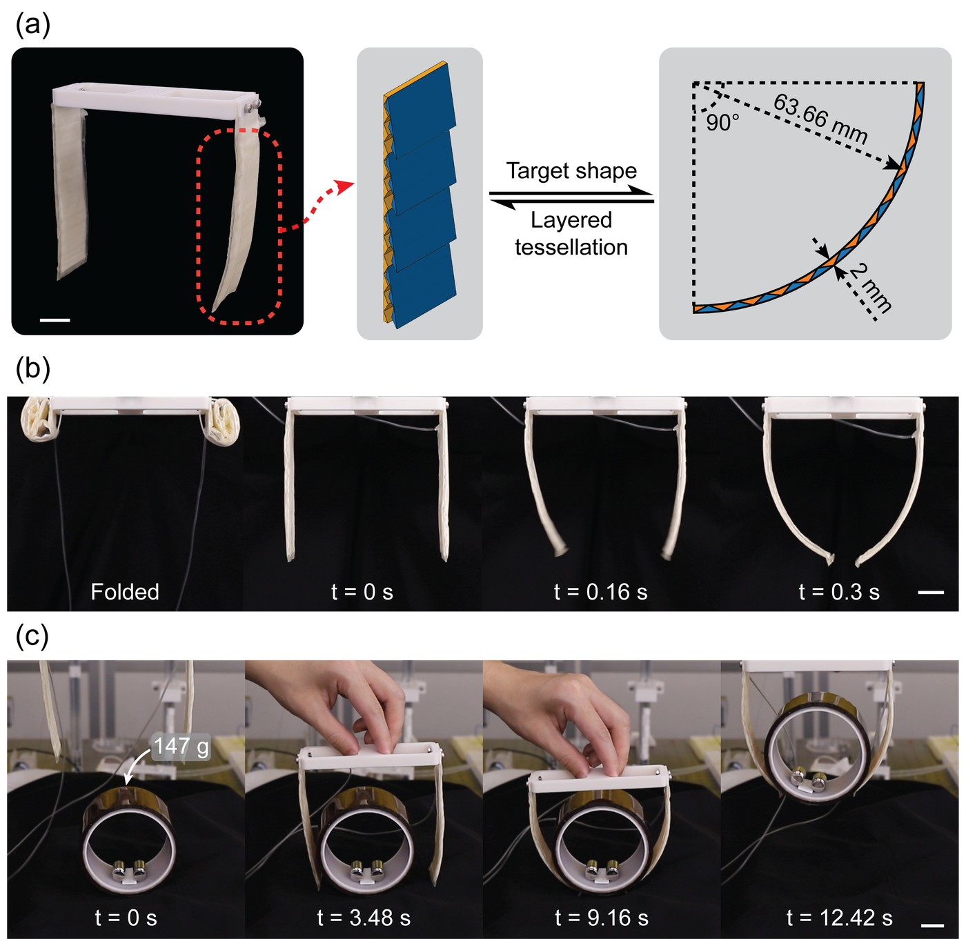
The gripper, the scaled structure in one finger, and the finger's quarter-circle target
The gripper, the scaled structure in one finger, and the finger's target shape. Scale bar, 2 cm. Adapted from Chen et al., International Journal of Mechanical Sciences 284, 109699 (2024). Full figure
The fingers curl into a quarter circle within a quarter of a second, then open again when the pressure is released (real time). Recorded for the paper.
The gripper closes around a 147 g load and lifts it (real time). Recorded for the paper.

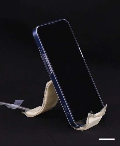
The phone stand is one strip of eight scales with two periods each, 4 mm thick and 3 cm wide. It takes its shape in about 11 s and then holds a phone.
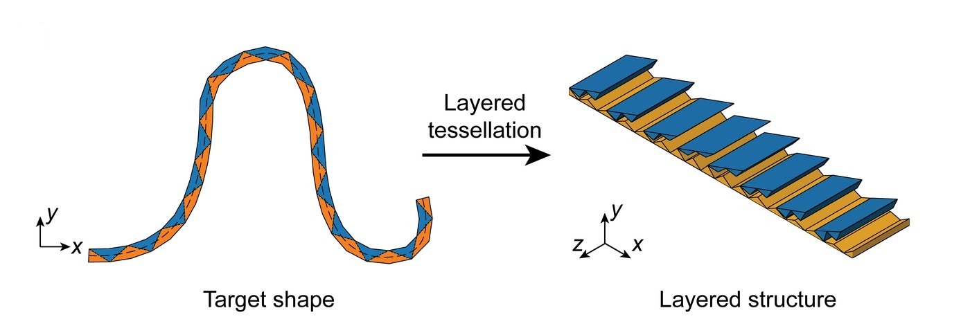
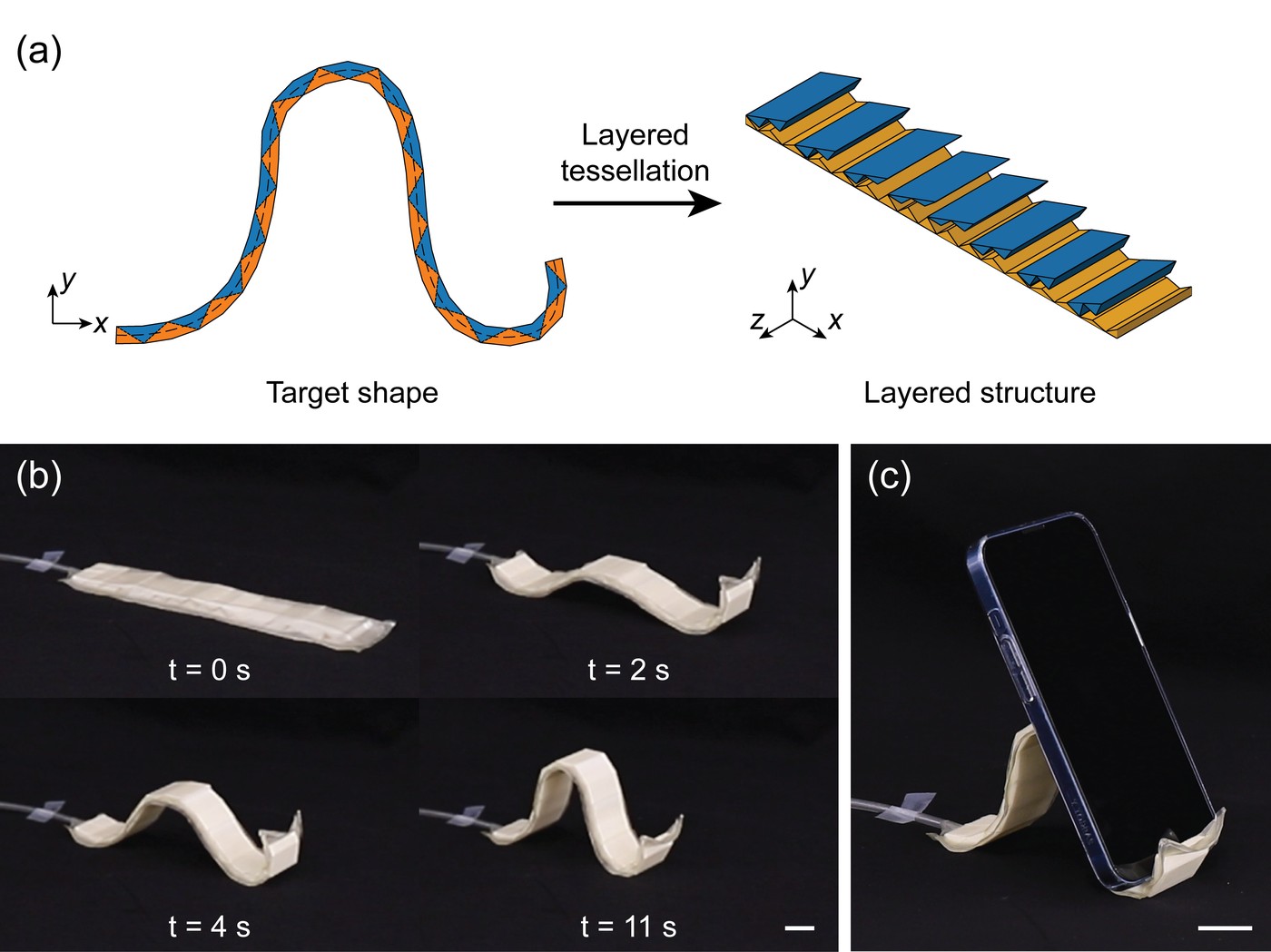
The phone stand's target shape and its layered structure
The phone stand's target shape and the layered structure designed from it. Adapted from Chen et al., International Journal of Mechanical Sciences 284, 109699 (2024). Full figure
The flat strip morphs into the phone stand (real time). Recorded for the paper.
A phone resting on the stand
The stand holding a phone. Scale bar, 2 cm. Adapted from Chen et al., International Journal of Mechanical Sciences 284, 109699 (2024). Full figure

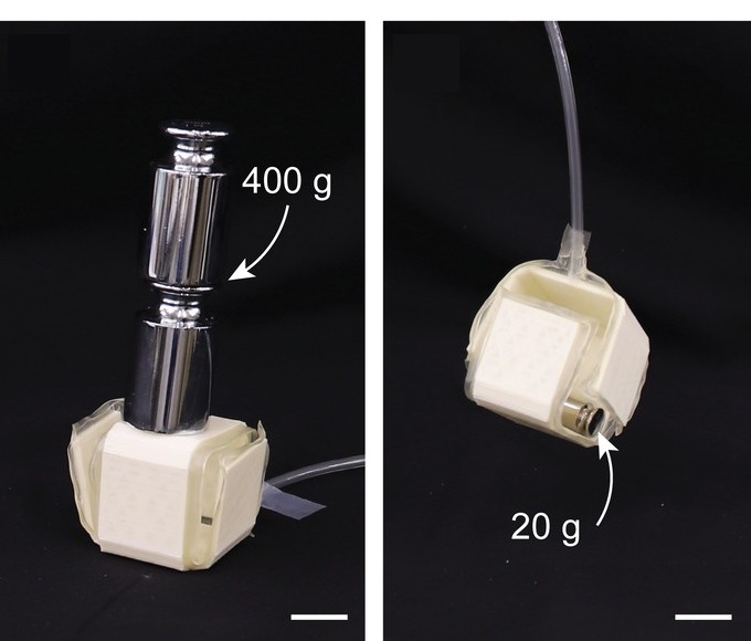
In the box, the scaled structures are only the hinges, each designed as a quarter circle, between flat faces 2 mm thick and 3 cm wide. The box folds within one second, holds 400 g, and lifts 20 g.
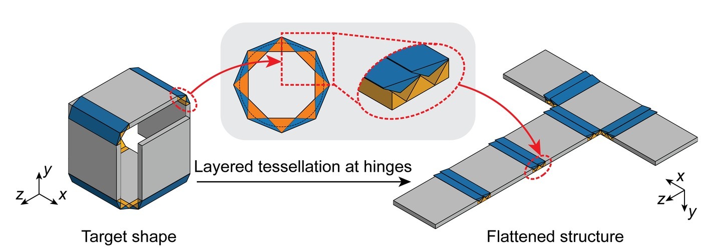
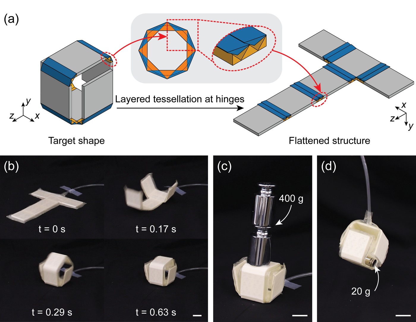
The folded box, a hinge's layered tessellation, and the flat sheet
The box, the layered tessellation at its hinges, and the flat sheet it folds from. Adapted from Chen et al., International Journal of Mechanical Sciences 284, 109699 (2024). Full figure
The flat sheet folds into a box within one second (real time). Recorded for the paper.
The folded box under a 400 g weight, and lifting a 20 g weight
The folded box holds 400 g (left) and lifts 20 g (right). Scale bars, 2 cm. Adapted from Chen et al., International Journal of Mechanical Sciences 284, 109699 (2024). Full figure

BibTeX #

@article{chen2024design,
  title = {Design and modeling of a programmable morphing structure with variable stiffness capability},
  author = {Chen, Tianyu and Yang, Xudong and Wang, Yifan},
  journal = {International Journal of Mechanical Sciences},
  volume = {284},
  pages = {109699},
  year = {2024},
  doi = {10.1016/j.ijmecsci.2024.109699}
}