Tianyu Chen Scale-inspired programmable robotic structures

Scale-inspired programmable robotic structures with concurrent shape morphing and stiffness variation

Tianyu Chen, Xudong Yang, Bojian Zhang, Junwei Li, Jie Pan, Yifan Wang*

School of Mechanical and Aerospace Engineering, Nanyang Technological University, Singapore

*Corresponding author: yifan.wang@ntu.edu.sg

Science Robotics 9, eadl0307 (2024)

The landing gear unfolds in flight and the drone lands on it (4× speed; the hover in between is cut).

Summary

Animals such as the octopus change their shape and their stiffness at the same time, with one integrated body. Soft robots usually need separate modules for the two, which makes them bulky and their control complex. This paper presents SAILS, a scale-inspired layered structure that does both with a single input. Its scales carry inversely designed surface patterns. Sealed in a thin latex envelope, the structure is soft until a negative pressure is applied; then it takes its programmed shape and becomes stiff.

Because it runs on negative pressure, SAILS does not inflate: it stays as thin as about 1 mm and can be actuated at up to 5 Hz. The paper uses it for an amphibious soft robot and for drone landing gear that adapts to different loads.

1 Working principle #

SAILS is a base layer with a row of scales attached to it, both printed from TPU and covered with PTFE tape to reduce friction. Each scale is bonded to the base layer on one side, and the whole structure is sealed between two latex films. With no pressure applied, the scales and the base layer are barely coupled, so the structure can be rolled up or sag under its own weight. A negative pressure of 90 kPa presses the patterned surfaces together until they interlock: the structure takes the shape its patterns were designed for and becomes stiff.
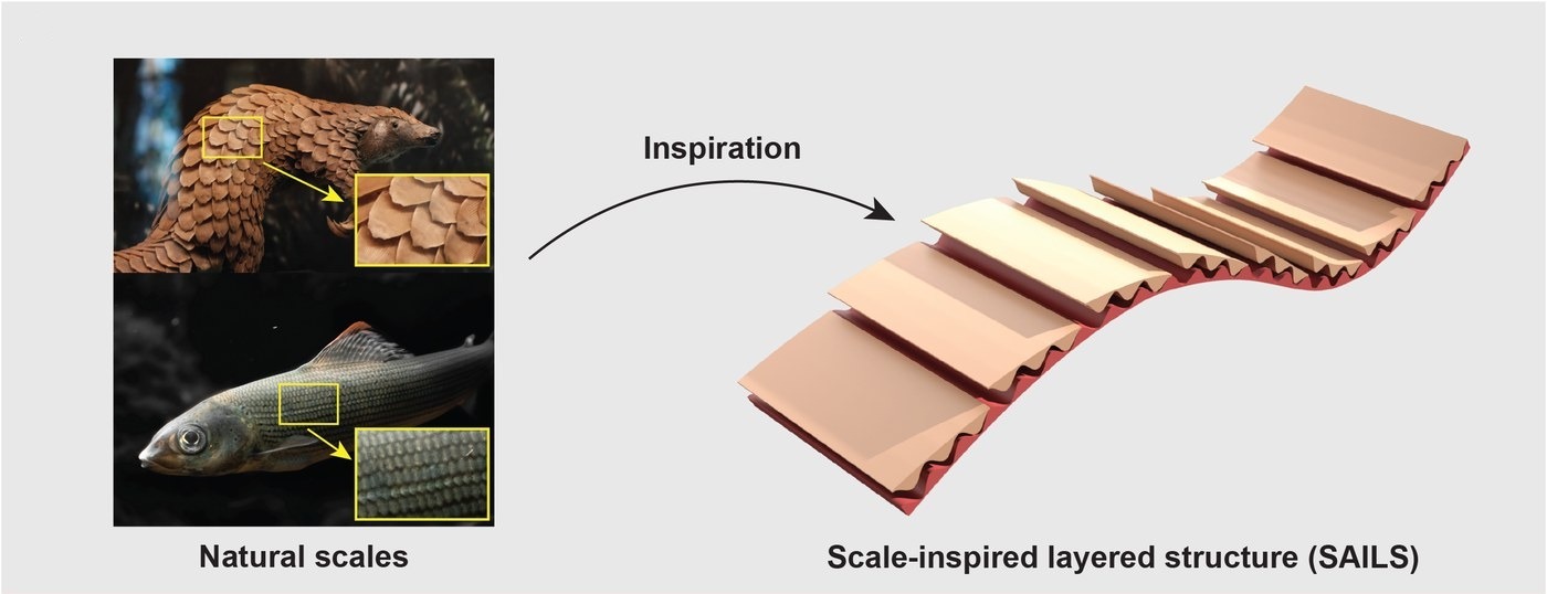
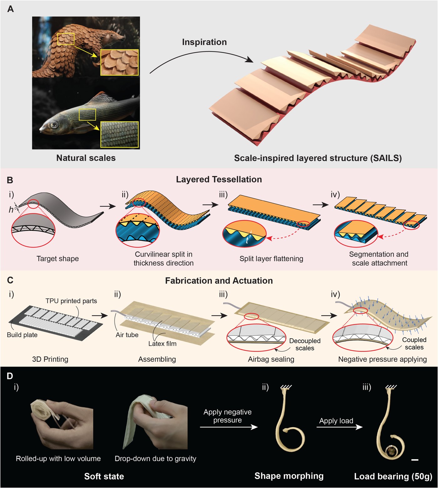
Pangolin and fish scales, and the scale-inspired layered structure they inspired
The scales of pangolins and fish, and the layered structure they inspired. Adapted from Chen et al., Science Robotics 9, eadl0307 (2024). Full figure

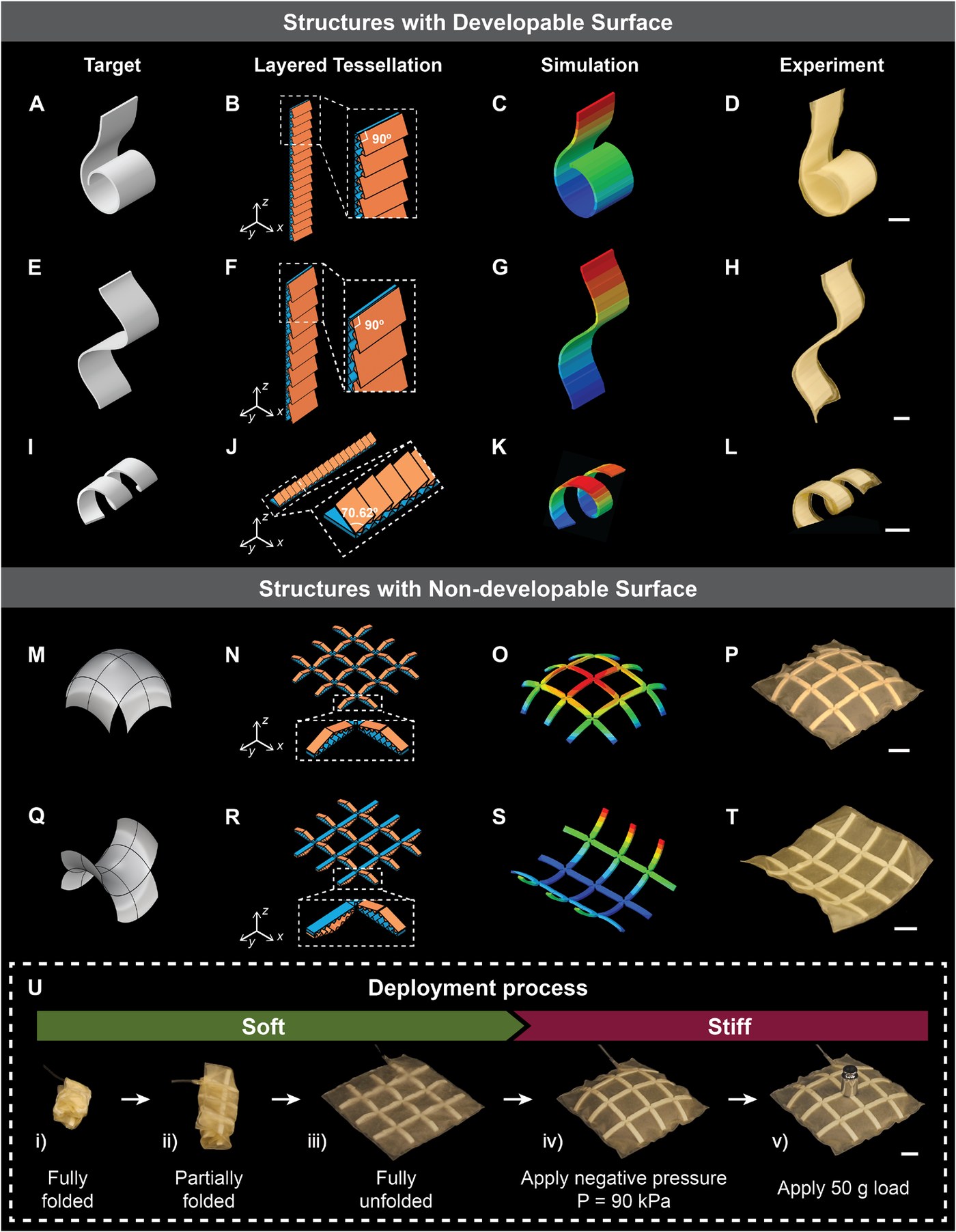
The patterns come from the target shape itself, by a method the paper calls layered tessellation. A sinusoidal cutting surface drawn along the middle of the target splits it into two layers. Each layer is divided into small units and flattened by rotating them, a thin supporting sheet is added to its back, and the upper layer is cut into scales short enough that their patterns still match the base layer when the structure lies flat. Pressed back together, the patterns mesh fully only in the shape they were cut from, which is why the structure returns to it.
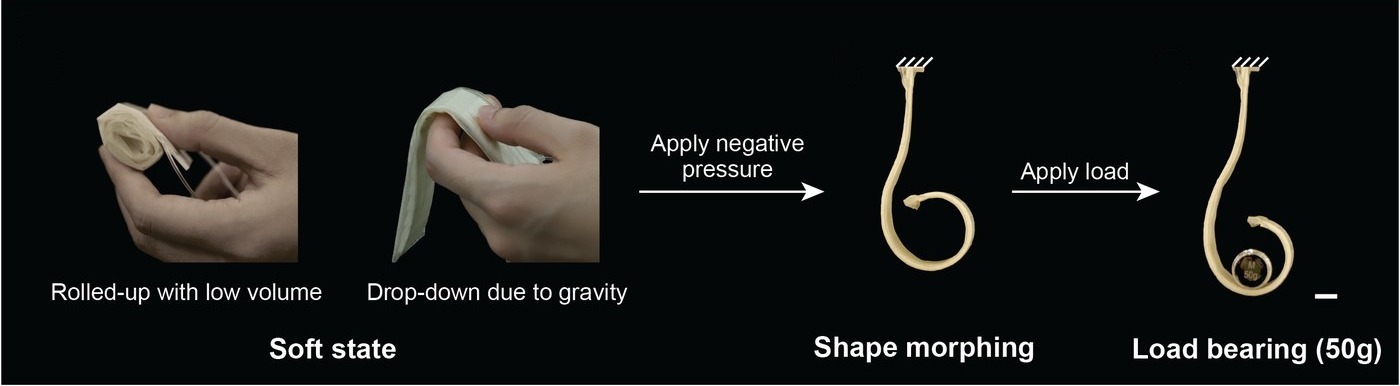
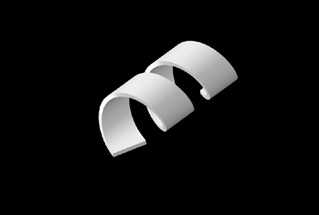
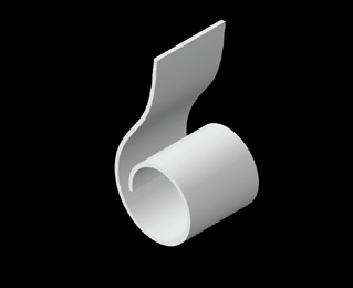
IllustrationLayered tessellation of the paper's hook, drawn to the dimensions in its supplementary materials (a 1.8 mm thick strip whose centerline is a spiral) with its 15 scales of 3 periods: the cut, the two flattened layers, the scales hinged to the base, and the strip curling back into its hook when the air is pumped out of its latex envelope. The last step shows the paper's 50 g load test. The circle magnifies one scale's hinge. The supporting sheets' thickness, how the loose scales rest, the envelope's wrinkles, the clamp, the tube, the weight's size and the timing are schematic.
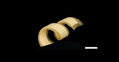
SAILS rolled up and hanging limp, then curled into a hook at 90 kPa and holding a 50 g weight
With no pressure, the strip can be rolled up or hangs limp; at 90 kPa it takes its hook shape and holds 50 g. Adapted from Chen et al., Science Robotics 9, eadl0307 (2024). Full figure
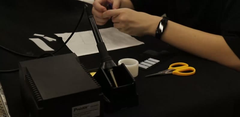
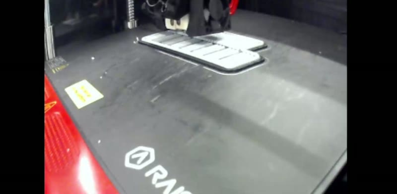
The printer laying down the scales and the base layer1  Print
Deburring the printed parts by hand2  Deburr
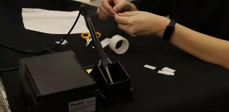
Covering the scales with PTFE tape3  Tape
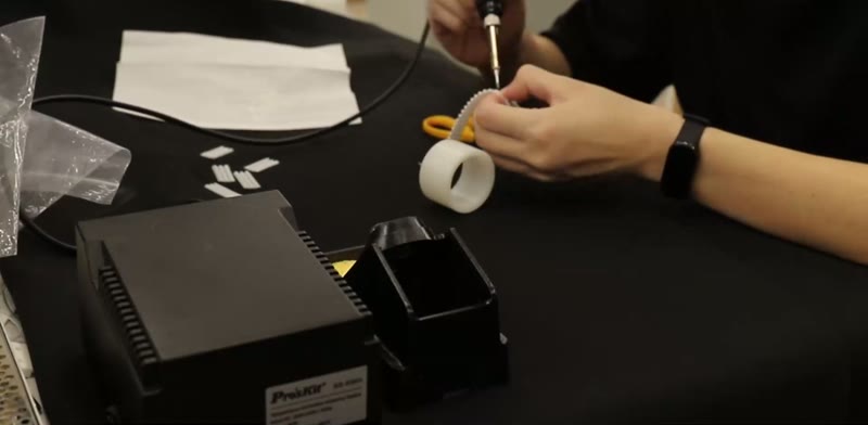
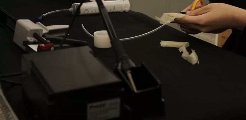
Bonding a scale to the base layer with a soldering iron4  Bond
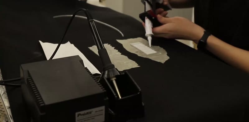
Sealing the structure between latex films with glue5  Seal
Trimming the excess latex film6  Trim and test
Making a SAILS, in stills from the movie below: printing the scales and the base layer in TPU, deburring them, covering the scales with PTFE tape, bonding each scale to the base layer on one side with a soldering iron, sealing the structure between two latex films with silicone glue, and trimming the films once the glue has cured. From Chen et al., Science Robotics 9, eadl0307 (2024).
How a SAILS is made, from printing to the first test. From Chen et al., Science Robotics 9, eadl0307 (2024).

2 Programmed shapes #

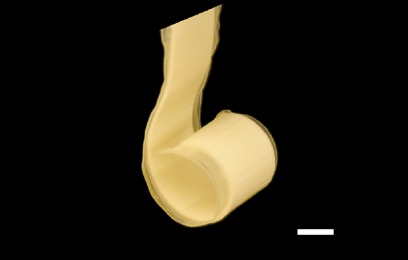
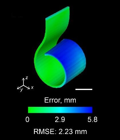
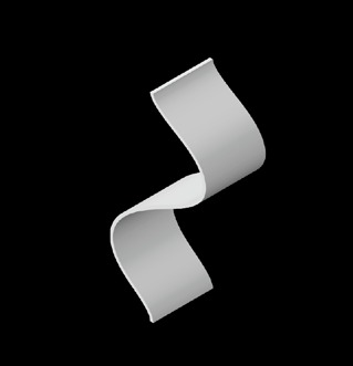
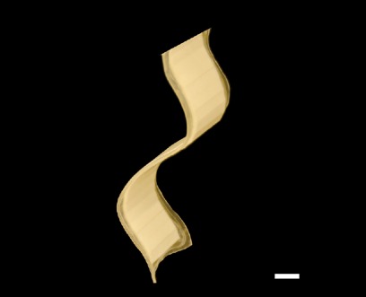
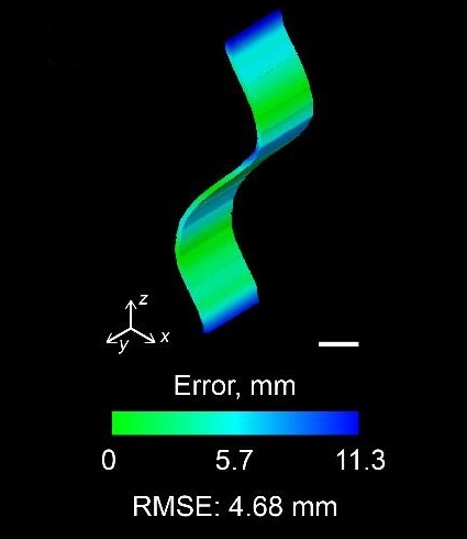
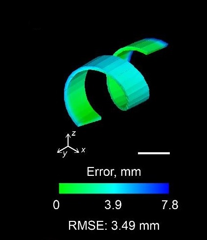
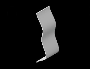
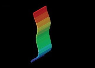
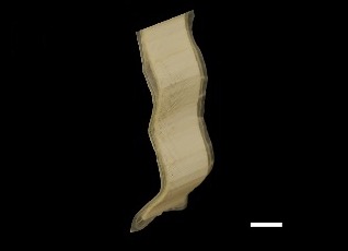
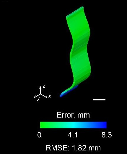
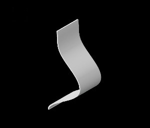
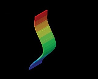
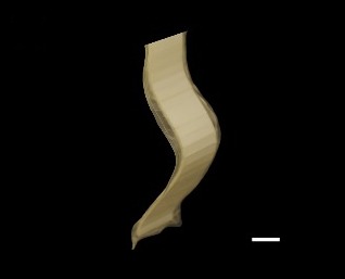
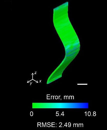
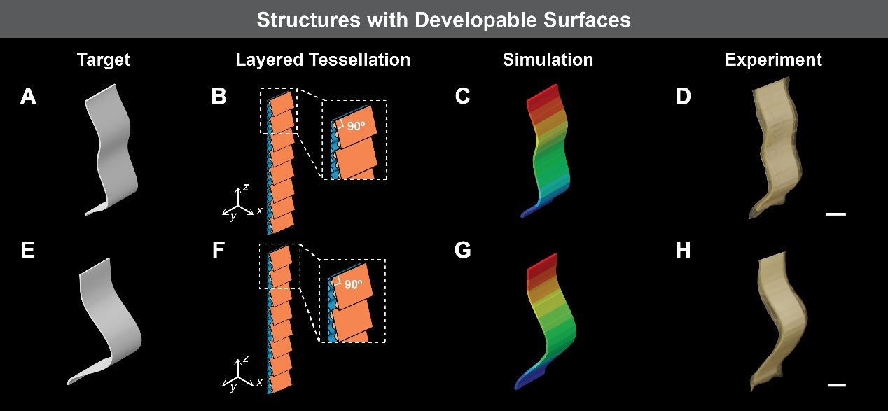
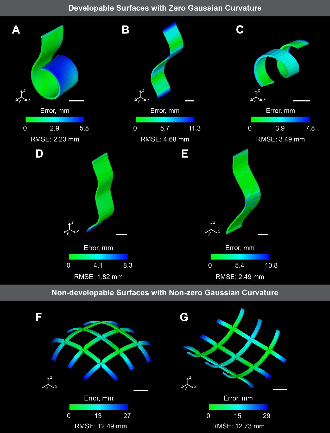
The same method programs many shapes. For surfaces that can be flattened without stretching, the target shapes, the finite element simulations and the experiments agree within a root mean square error of about 5%: a hook whose curvature grows toward its free end, a wave, a helix, which needs the patterns turned to 70.62°, and two surfaces defined by splines.

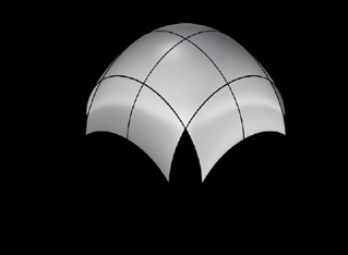
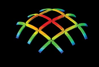
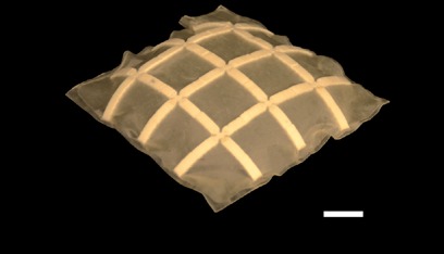
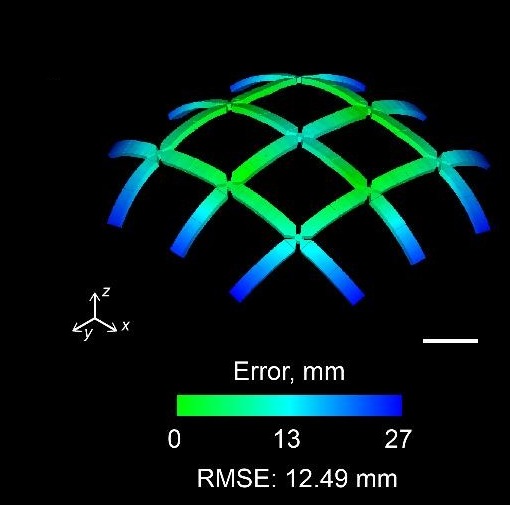
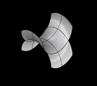
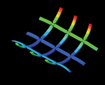
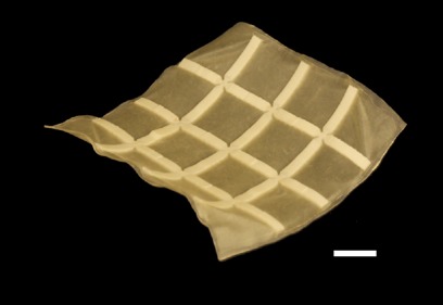
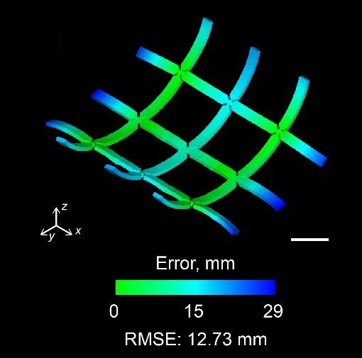
A single structure bends in only one direction, so domes and saddles are approximated with three-by-three meshes, to within about 10% of the target. The dome unfolds from a folded state and then holds 50 g, more than four times its own weight.

Hook
Hook, targetHook, simulationHook, experimentHook, distance between simulation and target

Wave

Wave, targetWave, simulationWave, experimentWave, distance between simulation and target

Helix

Helix, targetHelix, simulationHelix, experimentHelix, distance between simulation and target

Spline 1

Spline 1, targetSpline 1, simulationSpline 1, experimentSpline 1, distance between simulation and target

Spline 2

Spline 2, targetSpline 2, simulationSpline 2, experimentSpline 2, distance between simulation and target
Surfaces that can be flattened without stretching. The bottom row maps how far each simulation is from its target, with the root mean square error (RMSE). Scale bars, 2 cm. Adapted from Chen et al., Science Robotics 9, eadl0307 (2024), and its supplementary materials. Full figures: shapes, splines, errors.

Dome

Dome, targetDome, simulationDome, experimentDome, distance between simulation and target

Saddle

Saddle, targetSaddle, simulationSaddle, experimentSaddle, distance between simulation and target
Surfaces that cannot be flattened, built as three-by-three meshes. Scale bars, 2 cm. Adapted from Chen et al., Science Robotics 9, eadl0307 (2024), and its supplementary materials.
Structures with developable surfaces morphing into their target shapes, with simulations alongside the experiments. From Chen et al., Science Robotics 9, eadl0307 (2024).
Deployment of a dome-shaped structure, which then holds a 50 g load. From Chen et al., Science Robotics 9, eadl0307 (2024).

3 Stiffness variation #

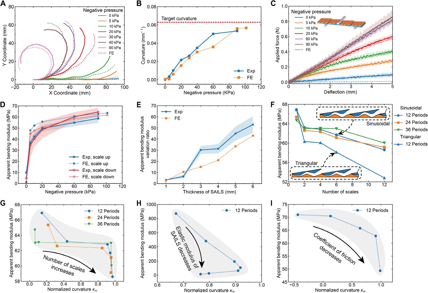
In three-point bending, a 2 mm thick structure with four scales stiffens as the pressure rises. Its apparent bending modulus goes from 9.8 MPa with no pressure to 36.8 MPa at 5 kPa and 58.7 MPa at 90 kPa, about six times, and it is similar whether the scales face up or down.
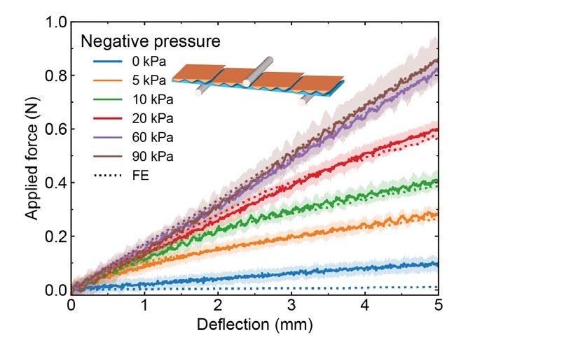
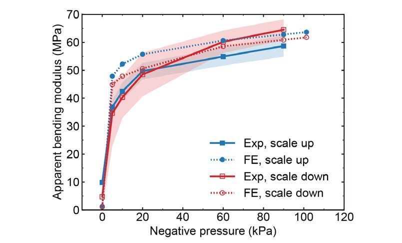
Force against deflection in three-point bending, from 0 to 90 kPa Apparent bending modulus against negative pressure, with the scales up or down
Left, force against deflection in three-point bending, from 0 to 90 kPa. Right, the apparent bending modulus against pressure, with the scales up or down. Adapted from Chen et al., Science Robotics 9, eadl0307 (2024). Full figure

Thicker structures stiffen much more. From 1 to 6 mm, the modulus at 90 kPa grows from a few times to 53 times the modulus with no pressure, more than the 10 to 26 times of many jamming-based structures, while SAILS stays among the thinnest of them.
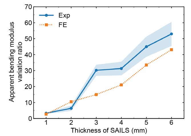
The ratio of the modulus at 90 kPa to the modulus with no pressure, against thickness, measured and simulated
The modulus at 90 kPa over the modulus with no pressure, against thickness: 53 times at 6 mm. Adapted from Chen et al., Science Robotics 9, eadl0307 (2024). Full figure

More scales make a structure softer but let it reach its target shape more closely, and changing the material's stiffness or the friction between the layers shows the same trade-off. The finite element models behind these results, in Abaqus/Explicit, are 3D for the shapes above and 2D plane strain for the bending tests. They treat the printed TPU as linear elastic (55.7 MPa) and the latex as neo-Hookean (1.1 MPa), use friction coefficients measured on an inclined plane, and reproduce both the bending tests and the morphed shapes.
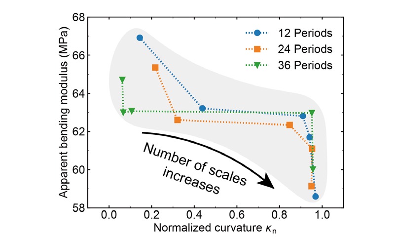
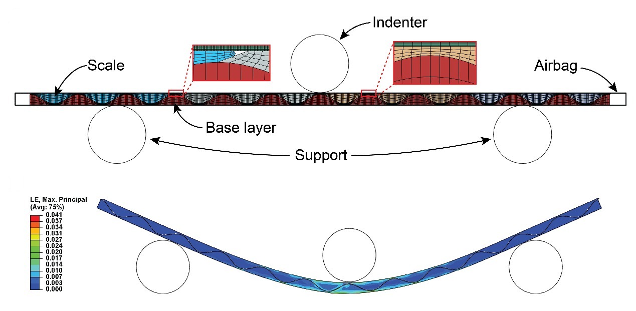
Bending modulus against normalized curvature as the number of scales grows The simulated three-point bending test and the strain in the structure
Left, the trade-off between stiffness and shape accuracy as the number of scales grows. Right, the simulated bending test: the scales, the base layer and the airbag on two supports under the indenter (top), and the largest principal strain at 90 kPa (bottom). Adapted from Chen et al., Science Robotics 9, eadl0307 (2024), and its supplementary materials. Full figure

4 An amphibious soft robot #

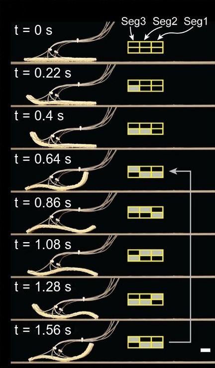
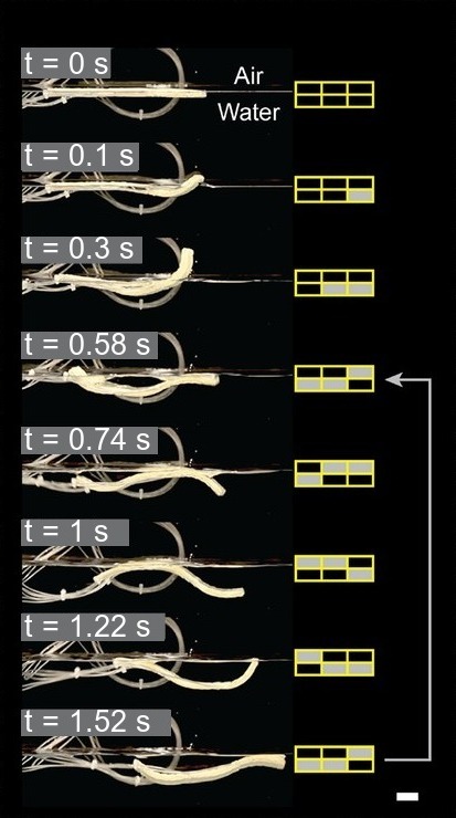
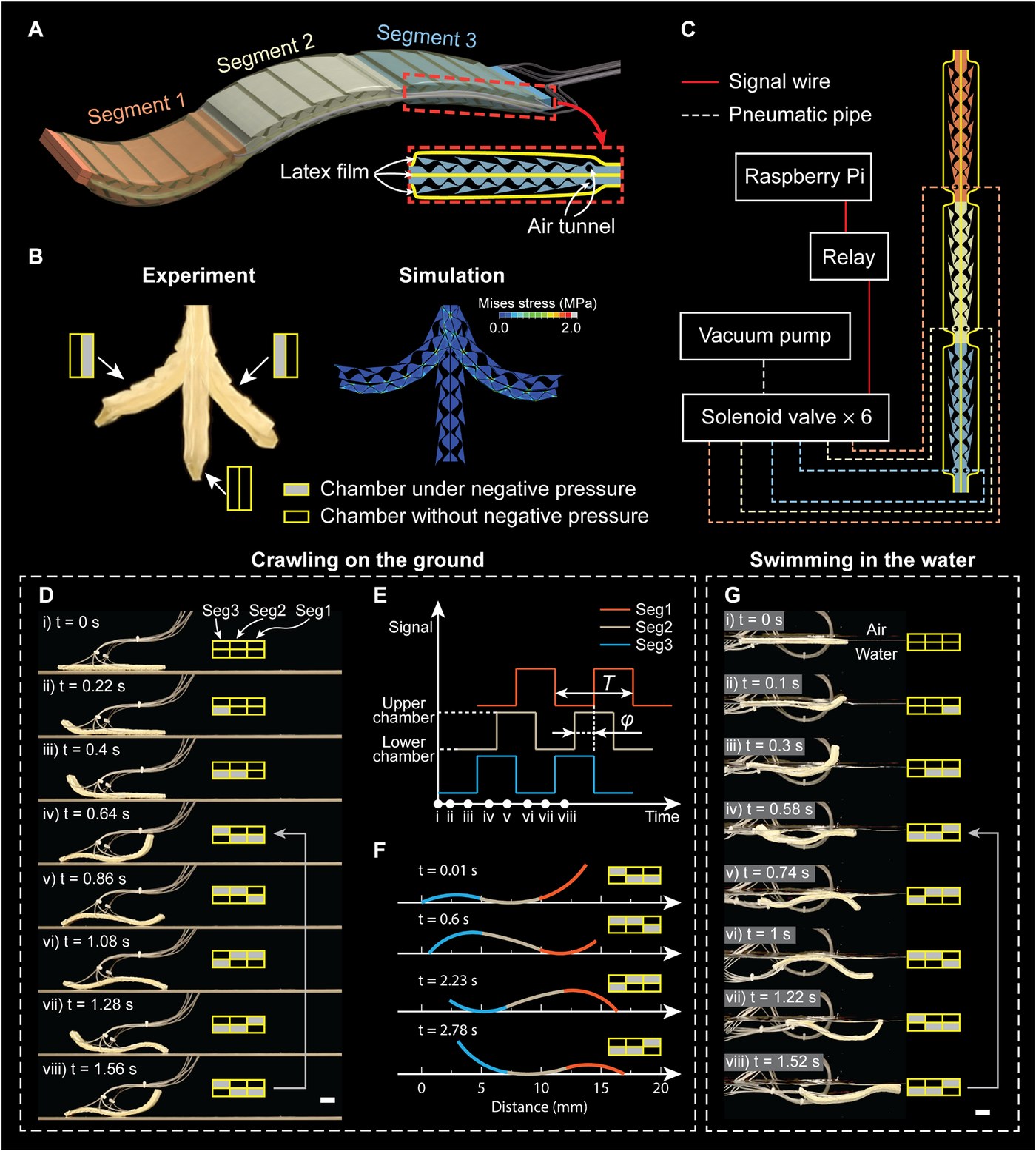
Three segments of SAILS, each with a chamber on either side, make a soft robot that moves like an eel or a snake. Actuating the chamber on one side or the other bends a segment up or down. A Raspberry Pi switches six solenoid valves on a vacuum pump. Actuating the chambers in turn, with each segment a quarter period behind the last, sends a wave along the body that drives the robot forward on ground; the reversed sequence makes it swim.
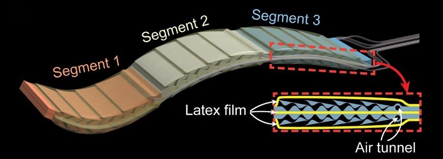
The robot's three segments, and a cross-section with its latex film and air tunnels
The robot's three segments, each with two chambers. Adapted from Chen et al., Science Robotics 9, eadl0307 (2024). Full figure
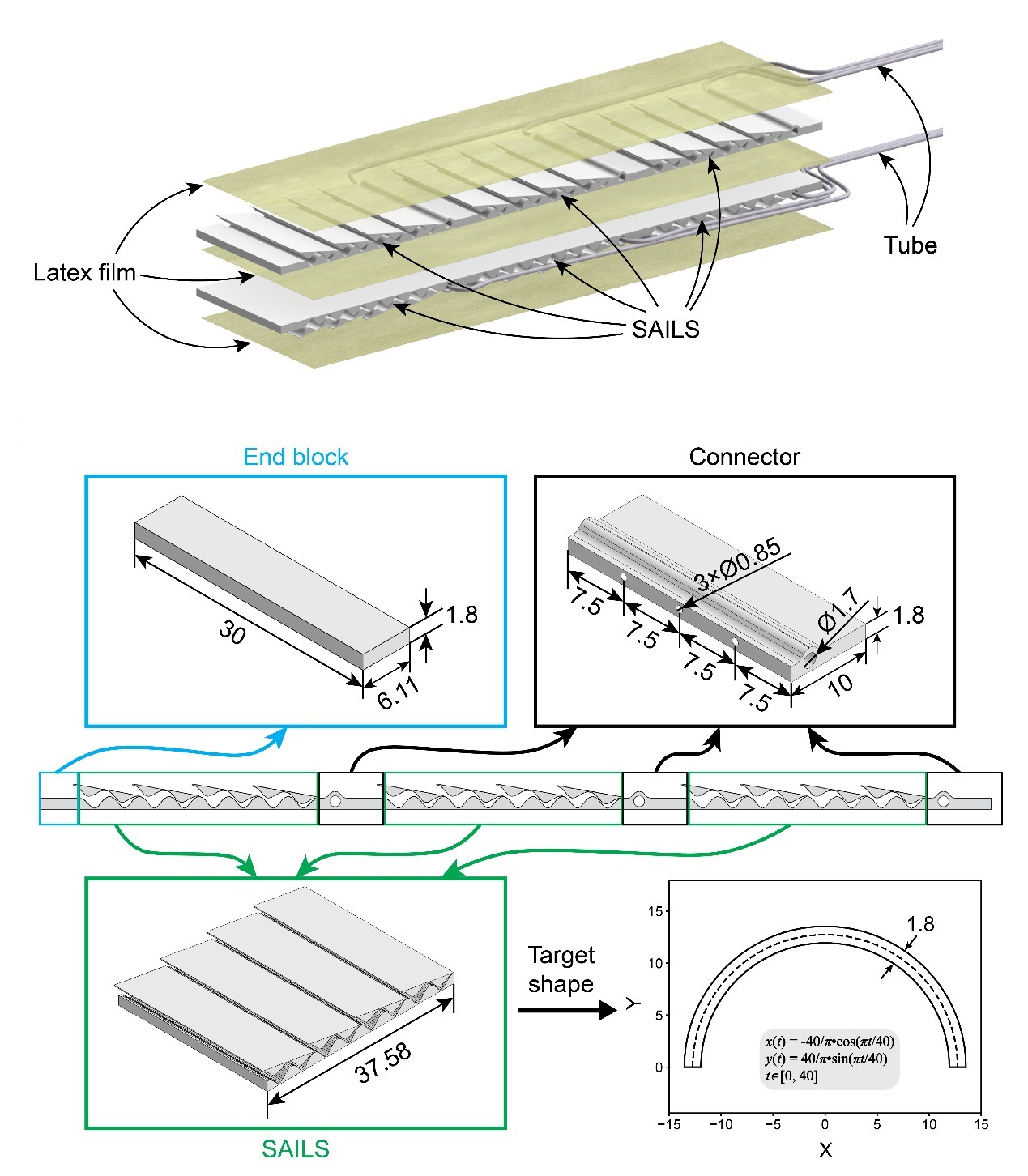
The robot's layers, and its printed parts with dimensions
The robot's layers (top): SAILS, latex films and air tubes. Below, the printed parts with their dimensions in mm, and the target shape of each SAILS segment. Adapted from Chen et al., Science Robotics 9, eadl0307 (2024), supplementary materials.
Snapshots of the robot crawling on the ground, with the chambers actuated at each moment Snapshots of the robot swimming in water, with the chambers actuated at each moment
Crawling on the ground, then swimming in water; the chambers under negative pressure are shaded at each moment. Adapted from Chen et al., Science Robotics 9, eadl0307 (2024). Full figure

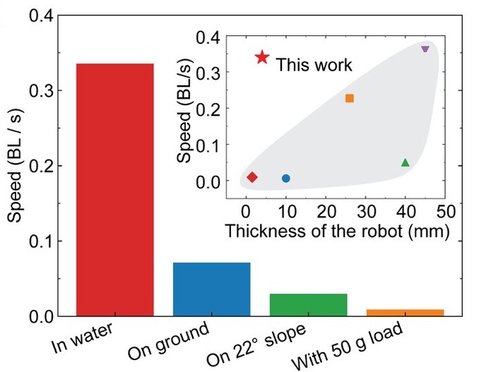
The robot climbs a 10 mm obstacle and crosses from land into water, squeezes through gaps that narrow from 20 to 8 mm, carries 50 g, nearly twice its own weight, and climbs a 22° slope. It is fastest at 0.56 Hz on ground and 1.25 Hz in water, where it reaches 0.34 body lengths per second, and models of both cases match the measured speeds.
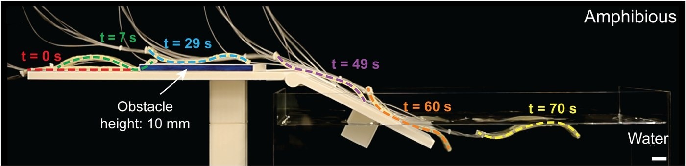
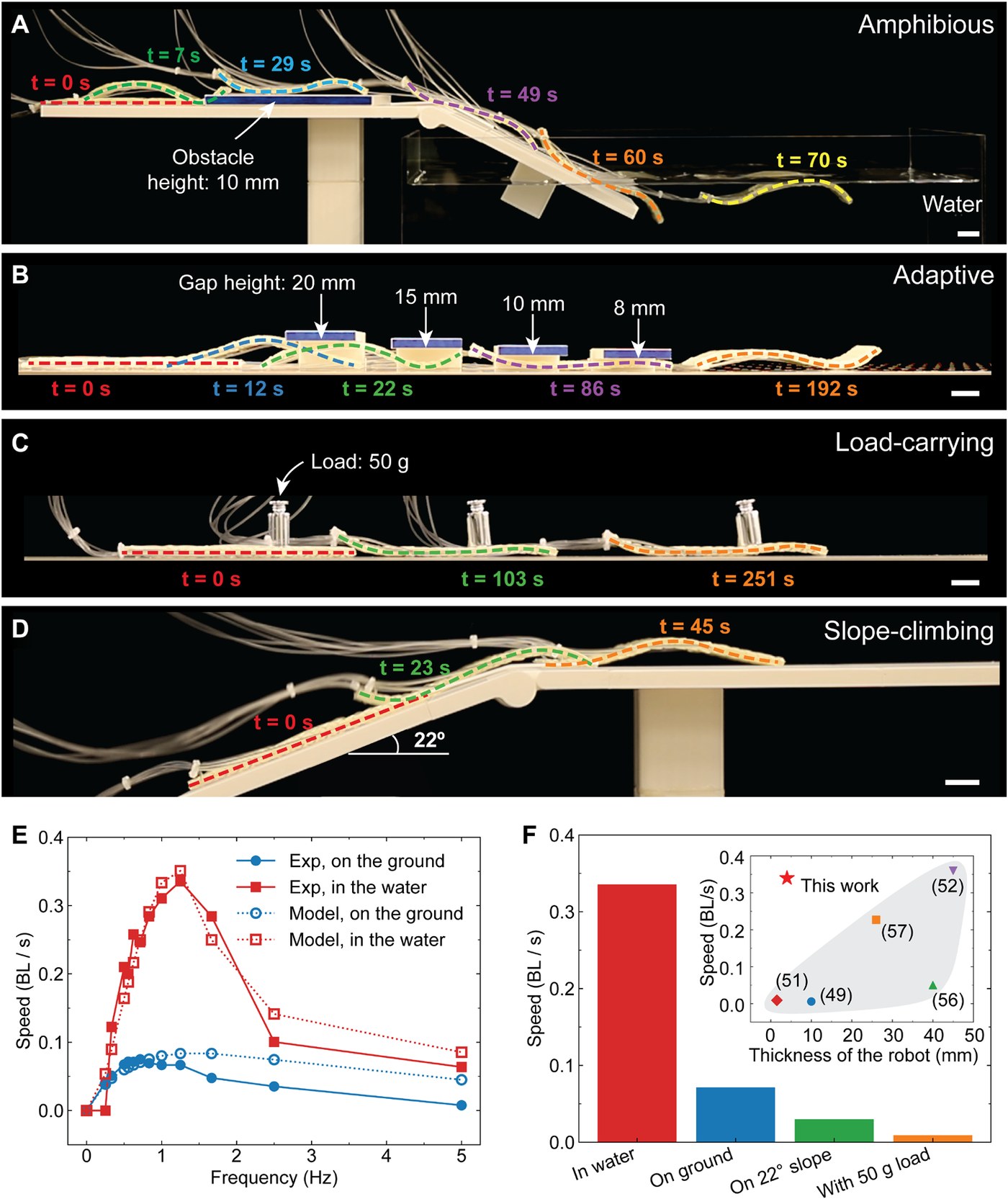
The robot climbing a 10 mm obstacle and moving into water, its outline traced over 70 s
The robot climbs a 10 mm obstacle and moves from land into water; its outline is traced at moments from 0 to 70 s. Adapted from Chen et al., Science Robotics 9, eadl0307 (2024). Full figure
Speed in water, on ground, on a slope and with a load; inset, speed against thickness for other soft robots
Speed in each scenario, in body lengths per second; inset, speed against thickness compared with other soft undulatory robots. Adapted from Chen et al., Science Robotics 9, eadl0307 (2024). Full figure
The amphibious robot crawling on the ground and swimming in water. From Chen et al., Science Robotics 9, eadl0307 (2024).
The robot climbing over an obstacle and moving from land into water. From Chen et al., Science Robotics 9, eadl0307 (2024).
The robot passing through gaps that narrow from 20 mm to 8 mm. From Chen et al., Science Robotics 9, eadl0307 (2024).
The robot carrying a 50 g load and climbing a 22° slope. From Chen et al., Science Robotics 9, eadl0307 (2024).

5 A bridge and a shield #

A larger robot, twice as thick and as wide and about twice as long, puts the stiffness to work. After crawling over an obstacle, it stiffens into a bridge for a toy car. It covers a quail egg and shields it from a falling 50 g ball that breaks the egg without protection, and it carries 1.26 kg, seven times its own weight.
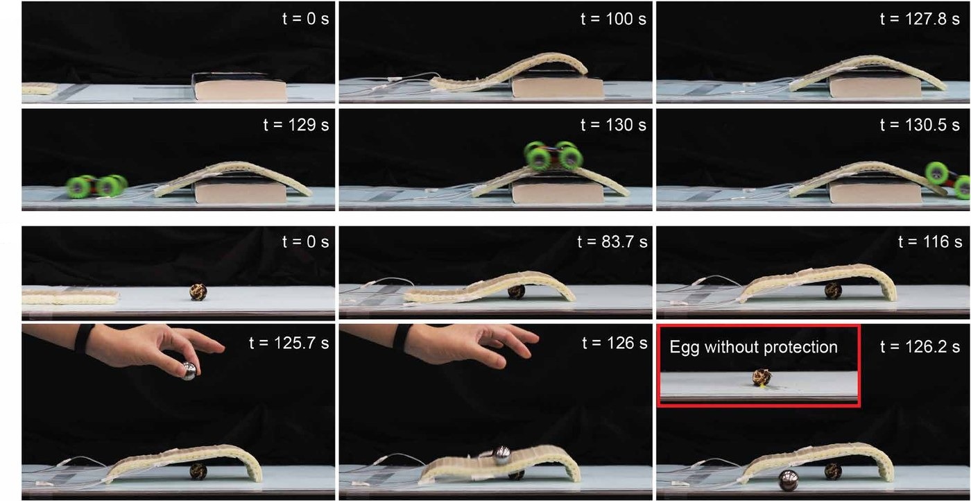
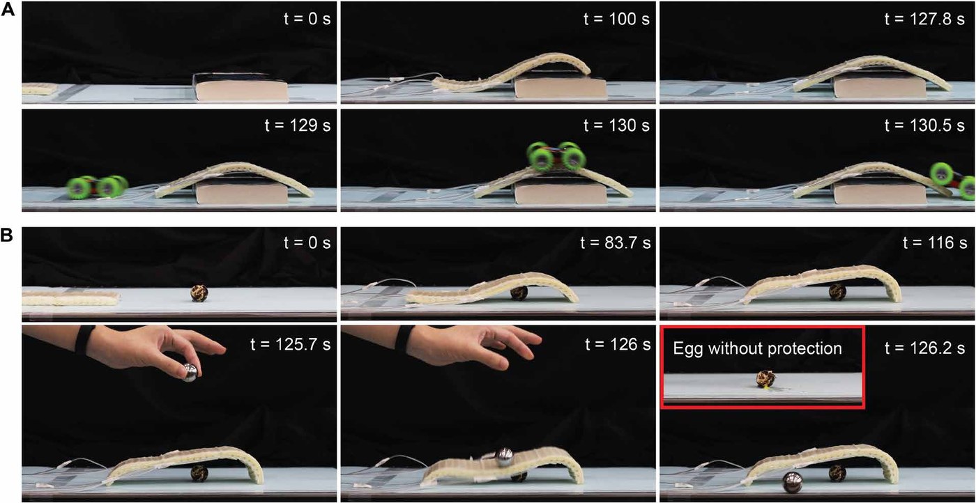
The robot as a bridge and as a protective structure
Top, the robot crawls over an obstacle and becomes a bridge for a toy car. Bottom, it covers a quail egg and shields it from a falling 50 g ball; without it, the ball breaks the egg. Adapted from Chen et al., Science Robotics 9, eadl0307 (2024). Full figure
A larger robot crawling over an obstacle, stiffening into a bridge for a toy car, shielding a quail egg from a falling ball and carrying a heavier load. From Chen et al., Science Robotics 9, eadl0307 (2024).

6 Adaptive landing gear for a drone #

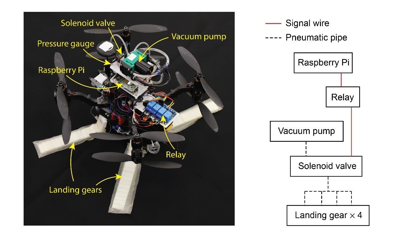
Hook-shaped landing gear made of SAILS turns its stiffness into adjustable impact protection. A Raspberry Pi, a vacuum pump, valves and a pressure gauge on the drone set the gear's pressure.
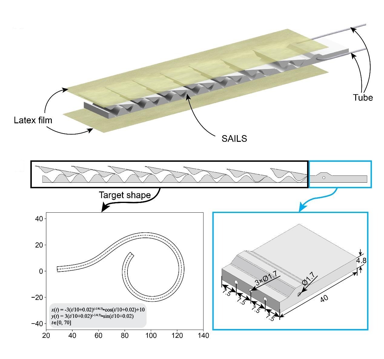
The landing gear's layers, and its printed layer with dimensions and target shape
The landing gear's layers (top): SAILS between latex films, with an air tube. Below, its printed layer and connector with dimensions in mm, and its target shape, a spiral. Adapted from Chen et al., Science Robotics 9, eadl0307 (2024), supplementary materials.
The drone from above with its pump, Raspberry Pi, relay, valve and gauge, and a diagram of how they connect
The drone from above, with its vacuum pump, Raspberry Pi, relay, solenoid valve, pressure gauge and landing gears, and how they connect. Adapted from Chen et al., Science Robotics 9, eadl0307 (2024), supplementary materials.
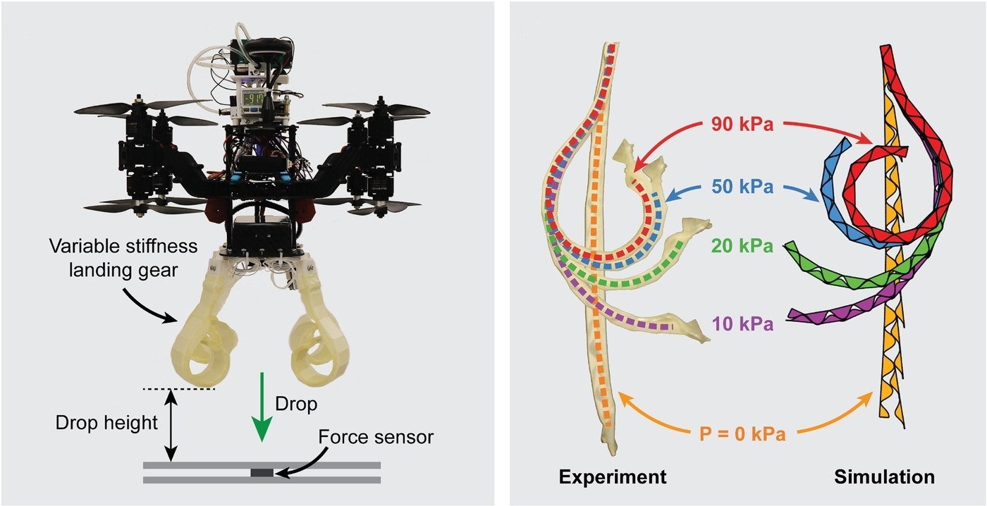
The drone with its landing gear above a force sensor, and the gear's shape from 0 to 90 kPa in experiment and simulation
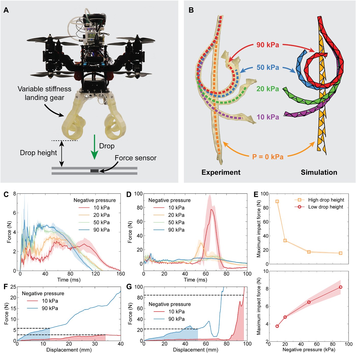
Left, the drop test: the drone and its landing gear above a force sensor. Right, the gear from 0 to 90 kPa, in experiment and simulation. Adapted from Chen et al., Science Robotics 9, eadl0307 (2024). Full figure

In drop tests, a stiffer gear gives a higher peak force when the drone falls 3 cm, but a lower one when it falls 20 cm. Simulations of the gear under compression explain why: at low pressure the soft gear collapses until its fixed end hits the ground, while the gear at 90 kPa does not. The gear deploys in flight before landing, and it also works as a gripper, lifting a 225 g load that the drone then carries off.
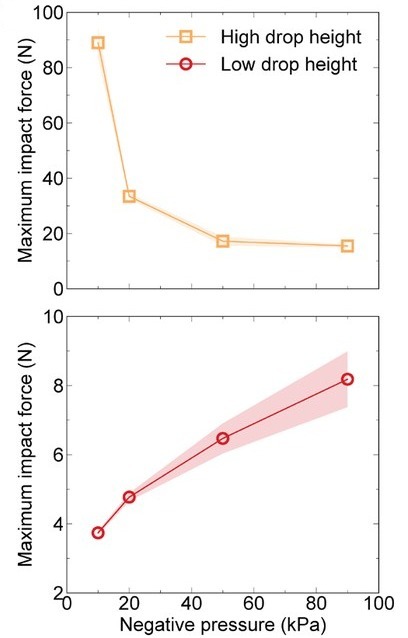
Highest impact force against pressure, falling as the gear stiffens for the high drop and rising for the low drop
The highest impact force against pressure, for the high drop (top, 20 cm) and the low drop (bottom, 3 cm). Adapted from Chen et al., Science Robotics 9, eadl0307 (2024). Full figure
Drop tests of the drone with its landing gear, released from 3 cm and 20 cm. From Chen et al., Science Robotics 9, eadl0307 (2024).
Setting the negative pressure in the landing gear with the onboard control system. From Chen et al., Science Robotics 9, eadl0307 (2024).
The landing gear deploying in flight, followed by the drone landing on it. From Chen et al., Science Robotics 9, eadl0307 (2024).
The landing gear working as a gripper to lift a 225 g load. From Chen et al., Science Robotics 9, eadl0307 (2024).

BibTeX #

@article{chen2024scale,
  title = {Scale-inspired programmable robotic structures with concurrent shape morphing and stiffness variation},
  author = {Chen, Tianyu and Yang, Xudong and Zhang, Bojian and Li, Junwei and Pan, Jie and Wang, Yifan},
  journal = {Science Robotics},
  volume = {9},
  number = {92},
  pages = {eadl0307},
  year = {2024},
  doi = {10.1126/scirobotics.adl0307}
}