Muscle coactivation-inspired stiffness-driven control strategy for antagonistic soft robots
School of Mechanical and Aerospace Engineering, Nanyang Technological University, Singapore
†Equal contribution
*Corresponding author: yifan.wang@ntu.edu.sg
Science Advances 12, eaeg3346 (2026)
Summary
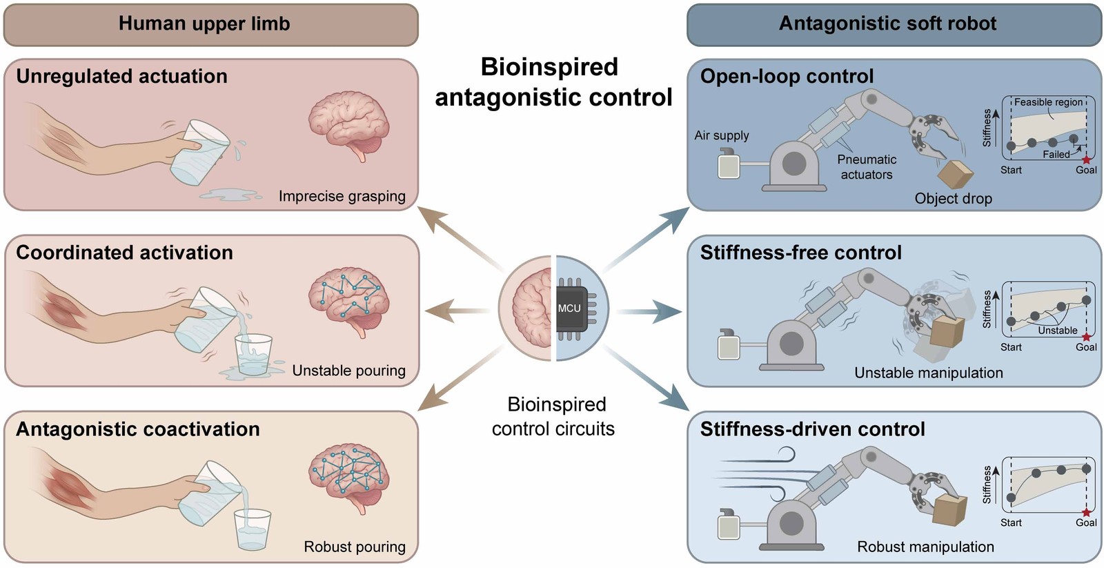
Soft robots are safe to work with and adapt to their surroundings, but they tend to carry little load and to lack precision. Antagonistic soft robots address this with opposing actuators: actuating one side bends the robot, and actuating both sides together stiffens it. Most controllers for such robots treat stiffness as a passive property, and those that do regulate it rely on analytical models of the robot and on measuring its stiffness in real time, which is hard for soft robots.
This paper borrows a strategy from human movement, muscle coactivation: tensing opposing muscles together makes a movement more precise. It presents a data-driven controller that regulates stiffness along with motion. The controller learns a Koopman model of the robot from a few minutes of simple motions, and its model predictive control rewards a large sum of the antagonistic inputs, which stiffens the robot. On a pneumatic robot built from scale-inspired layered structures, it tracks paths more accurately and holds its position under added loads better than controllers that ignore stiffness, and it lets the robot grasp objects, sense and sort them by stiffness, pump liquid and act as a reconfigurable bridge. The same strategy also controls a tendon-driven robot.
1 Antagonistic soft robot #
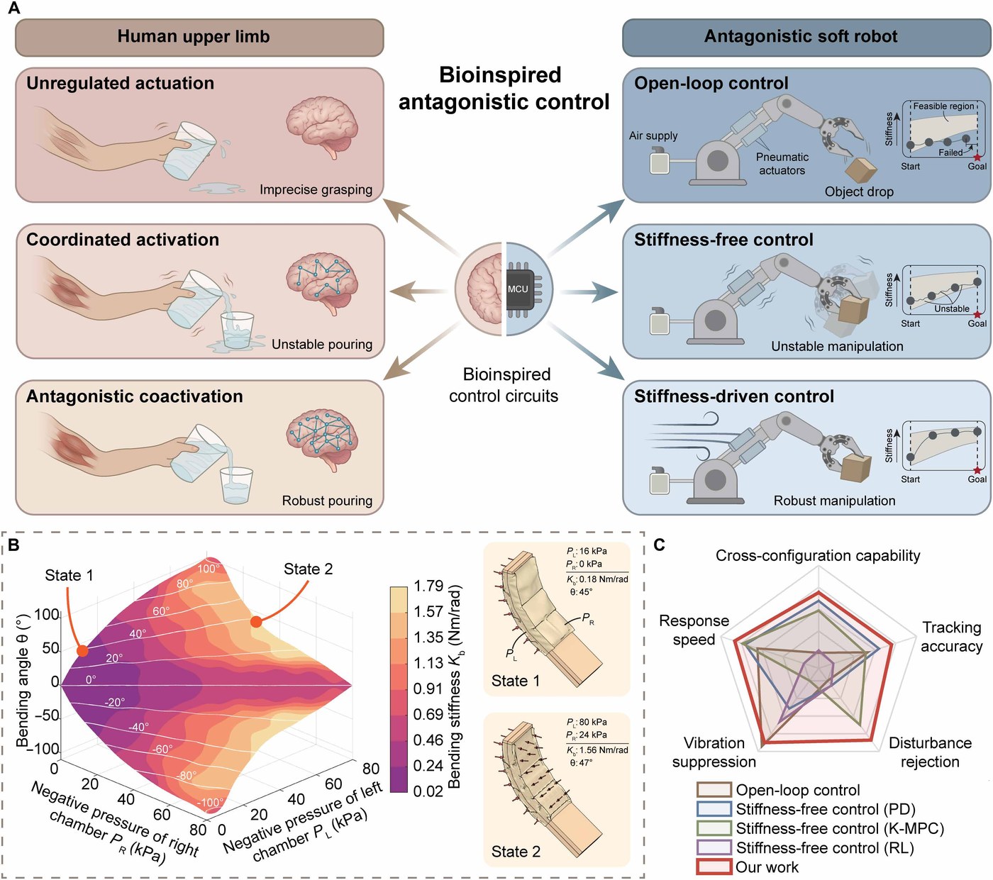
When a movement has to be precise, people stiffen their limbs by tensing opposing muscles together, and studies of arm movements show that this coactivation improves accuracy. The paper carries the idea to antagonistic soft robots, whose opposing actuators play the part of the muscles: actuating one side bends the robot, and actuating both stiffens it.
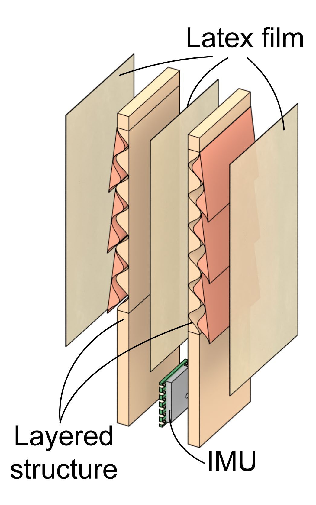
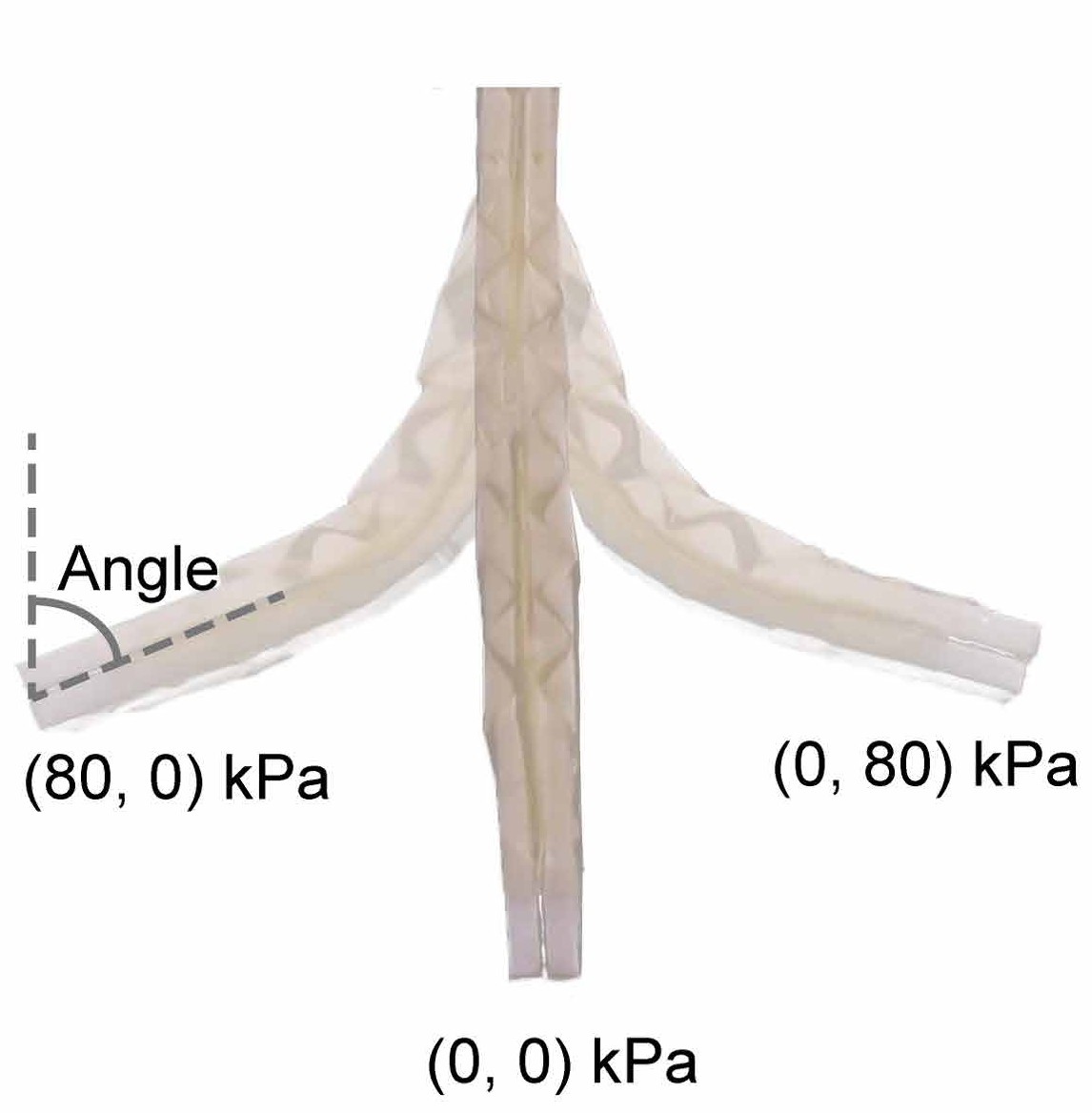
The robot is made of two units of the scale-inspired layered structure from an earlier paper. Each unit is a base layer with a row of scales, both carrying programmed surface patterns, printed in PLA and covered with 0.05 mm PTFE tape to reduce friction; the same tape attaches the scales to the base layer. Each unit is sealed between latex films with silicone glue, and the two units sit back to back, separated by a latex film, so the robot has two airtight chambers. A negative pressure in either chamber presses that unit's patterns together: the robot bends toward a programmed shape and stiffens at the same time. An inertial measurement unit (IMU) at the free end records the bending angle.
Finite element simulations map what the two pressures do. In two-dimensional plane strain models in Abaqus/Explicit, the robot hangs from its fixed base under gravity while each chamber holds a negative pressure between 0 and 80 kPa; the moment that turns the tip by a further 1°, divided by that angle, gives the bending stiffness. Across all pressure combinations the stiffness changes 88-fold, from 0.02 to 1.79 Nm/rad, and at a given bending angle it grows with the sum of the two pressures. The robot reaches about 45° with 16 kPa in the left chamber alone, at 0.18 Nm/rad, or with 80 and 24 kPa in the left and right chambers, at 1.56 Nm/rad.
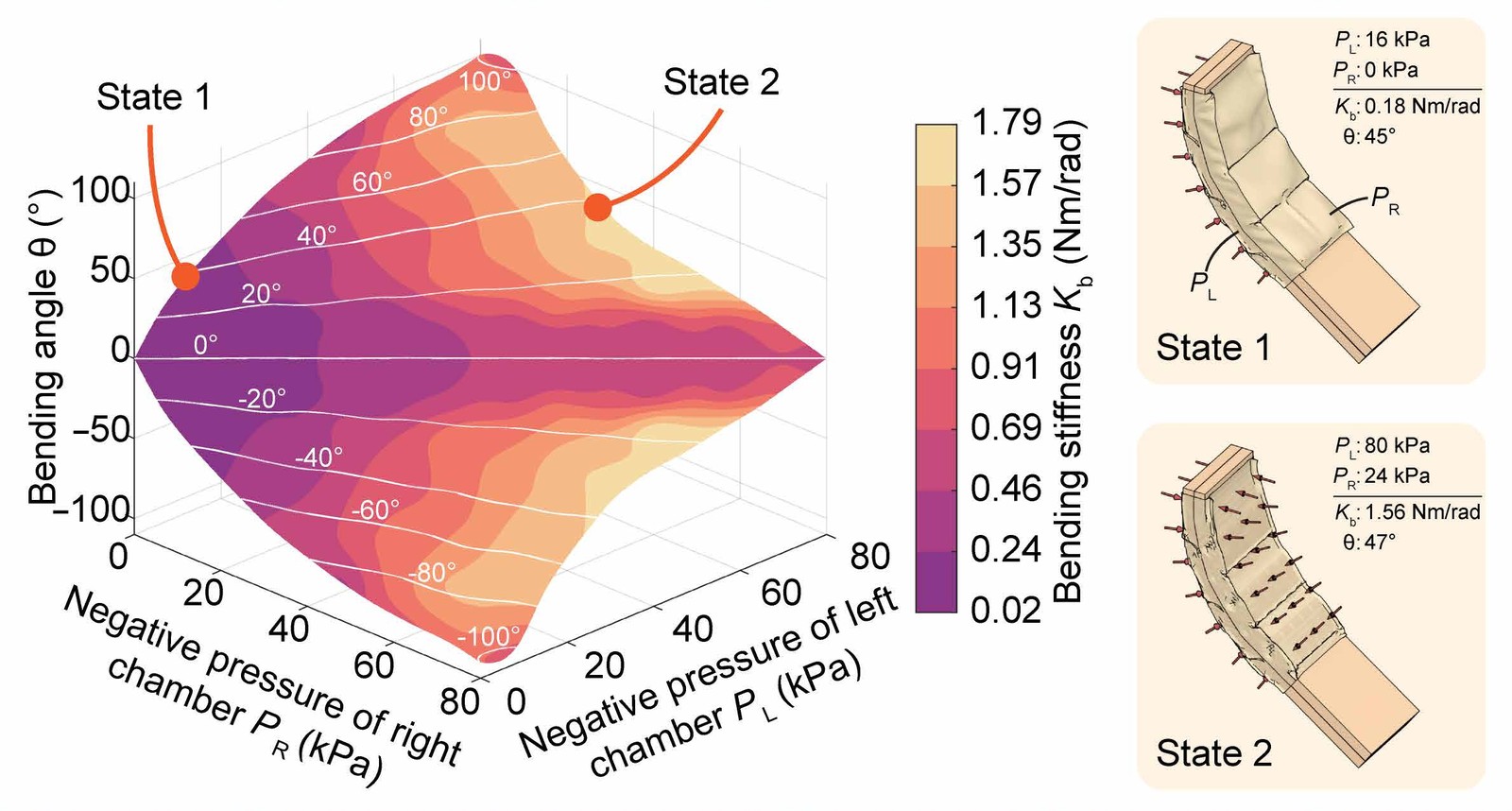
The same posture can therefore be soft or stiff. The controller exploits this freedom, but it also makes the motion less certain; together with the delay of pneumatic actuation and the fine input changes that small angles need, it makes such robots hard to control.
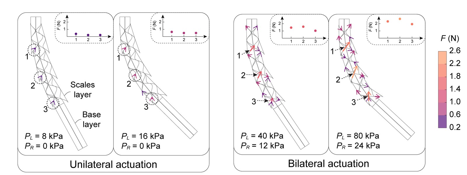
The simulations also show where the extra stiffness comes from. With both chambers depressurized, the friction forces between the scales and the base layer are about four times higher at three points along the robot than with one chamber, and the scales touch the base layer at more points, so the two engage more firmly.
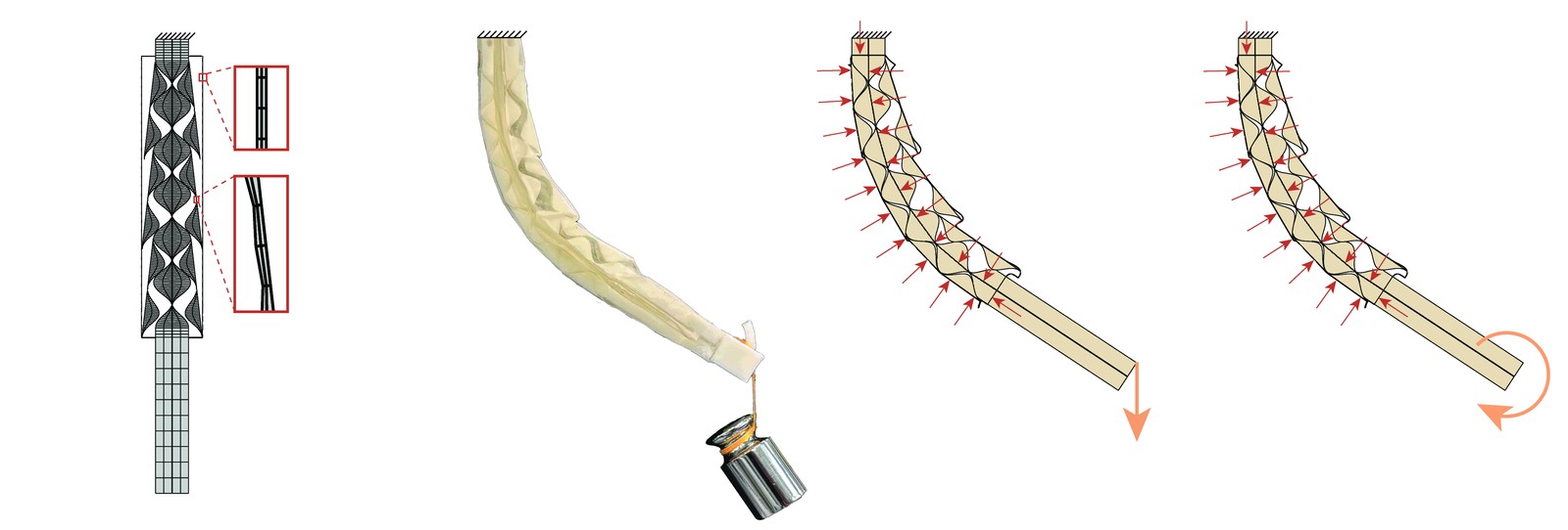
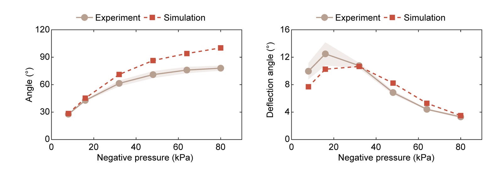
The model was checked against the real robot, mounted vertically: its bending angle as one chamber goes from 0 to 80 kPa, and the extra deflection when a 30 g weight hangs from its tip, each measured five times. The simulations follow the measured trends in both tests.
2 Stiffness-driven control #
The controller needs no model of the robot's mechanics. It learns the robot's dynamics from data: five 50 s trials sampled at 50 Hz, about 12,500 samples in all, in which the inputs follow two one-sided triangular waves and three sinusoids applied to both chambers with different phase offsets. Each sample holds the bending angle, the two inputs and the sampling interval. From these data, extended dynamic mode decomposition identifies a Koopman operator, which describes the nonlinear robot as a linear system in a lifted, higher-dimensional space and predicts its future states.
Three parts turn this model into a controller. For a system of mechanically independent robots, such as the gripper below, a decoupled bilinear lifting lifts each robot's own states and inputs separately, with polynomials of its current and past states and products of its states and previous inputs; for three robots, with three past states and polynomials up to third order, it shrinks the lifted space from 479 to 117 dimensions, which keeps the solver fast on embedded hardware. A stiffness-driven solver, a model predictive controller, minimizes the predicted tracking error and the changes of input, while a third term rewards a large sum of the two antagonistic inputs, the robot's counterpart of coactivation; a variant of this term sets a desired input sum, and with it a stiffness level. A deep Koopman feedforward compensator, whose lifting function is a neural network with three hidden layers, predicts the inputs a target state needs and amplifies them for large deflections, where the pneumatic robot responds slowly. It is trained offline on two more 50 s trajectories that start from high coactivation and gradually reduce one input.
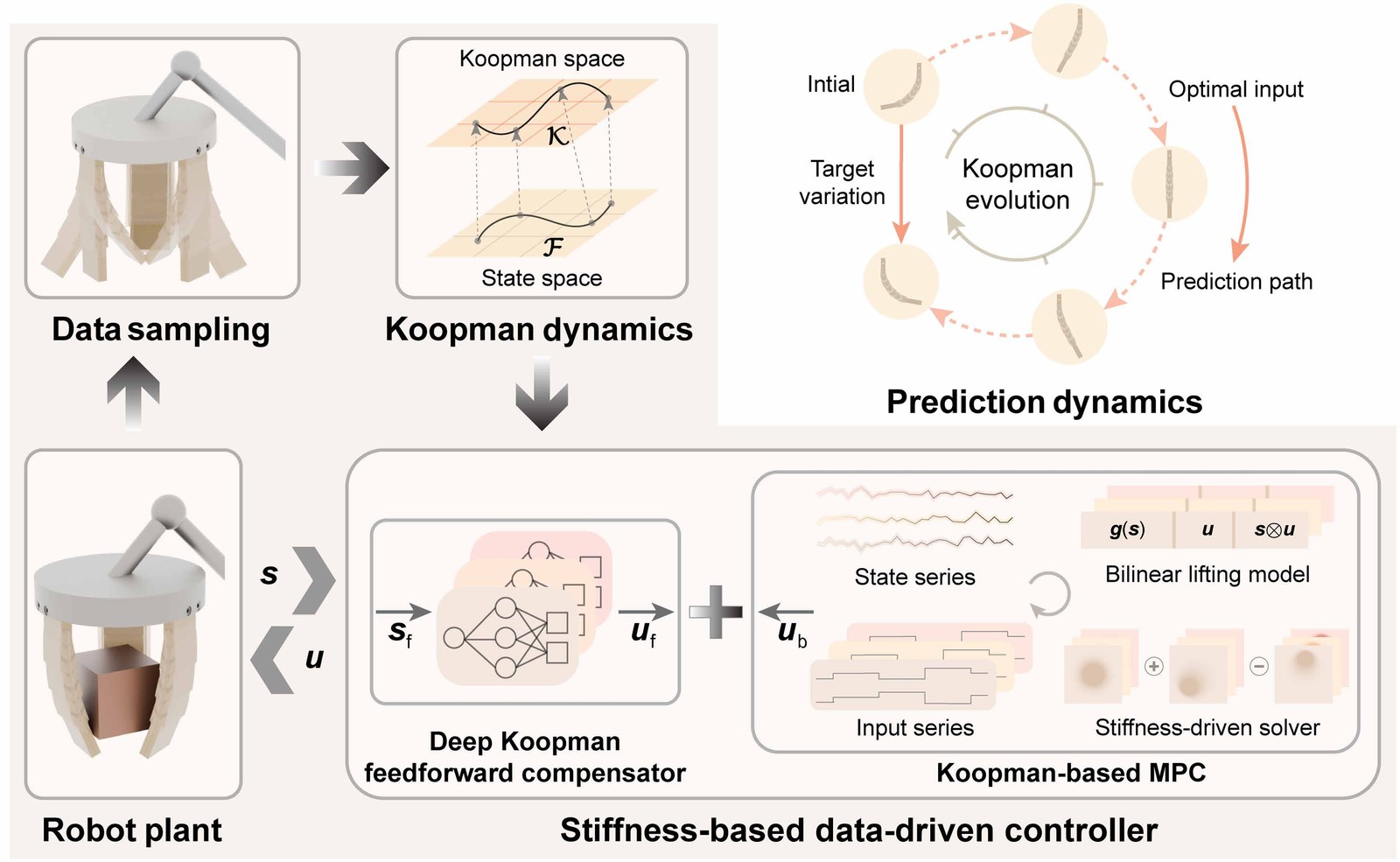
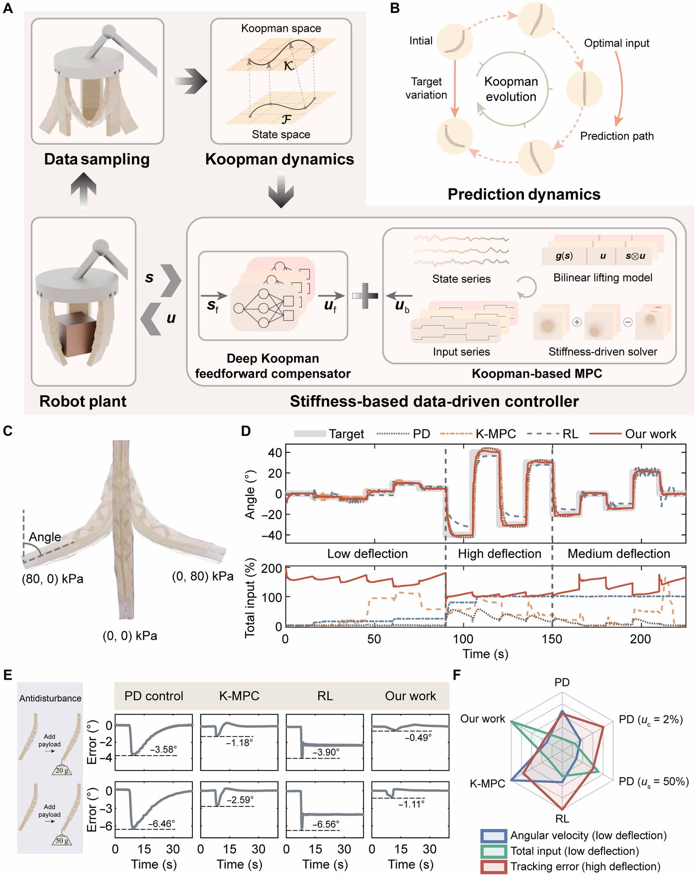
The penalty on input changes also gives the robot a sense of touch. In free motion it keeps the inputs steady; when the robot meets an object, the contact resists its motion, and the controller must change its inputs more to stay on its path. An input variation above 0.06% therefore signals contact, with no force sensor.
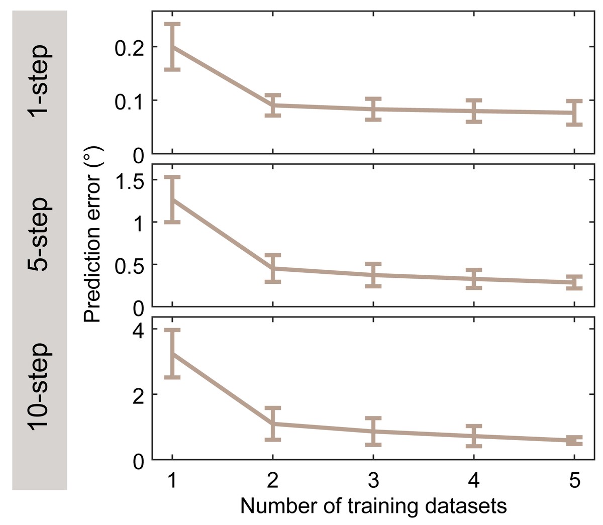
The controller is quick to set up. Collecting 250 s of data and building the Koopman matrices, which takes 39.86 s on a Raspberry Pi 4B, gives the prediction model in about 290 s. With another 100 s of data and 70.60 s to train the compensator on a separate computer, the full controller is ready in about 460 s, under eight minutes. It then runs at 50 Hz, taking 11.61 ms of each 20 ms step on average. More training data mainly helps longer predictions: the prediction error falls as trials are added, most clearly ten steps ahead.
3 Path tracking and disturbance rejection #
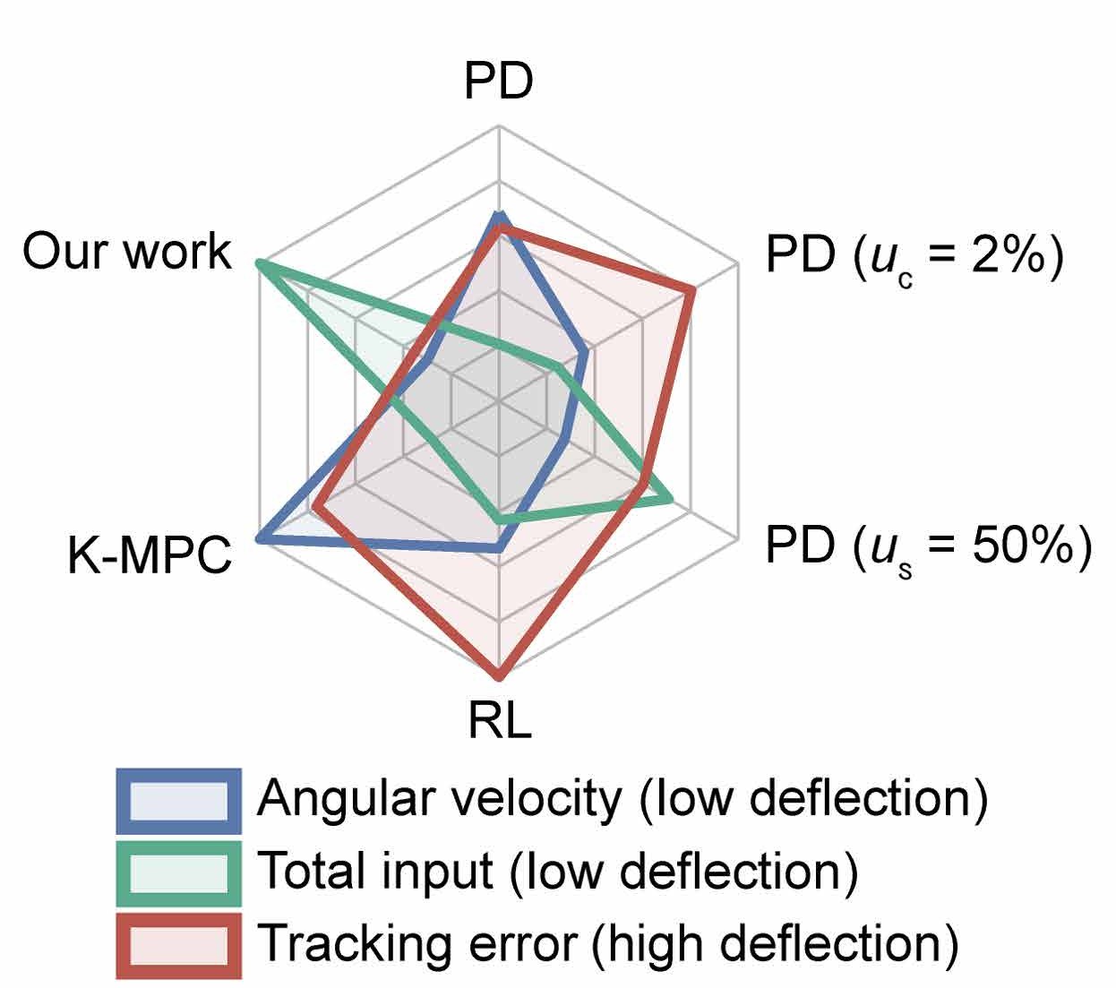
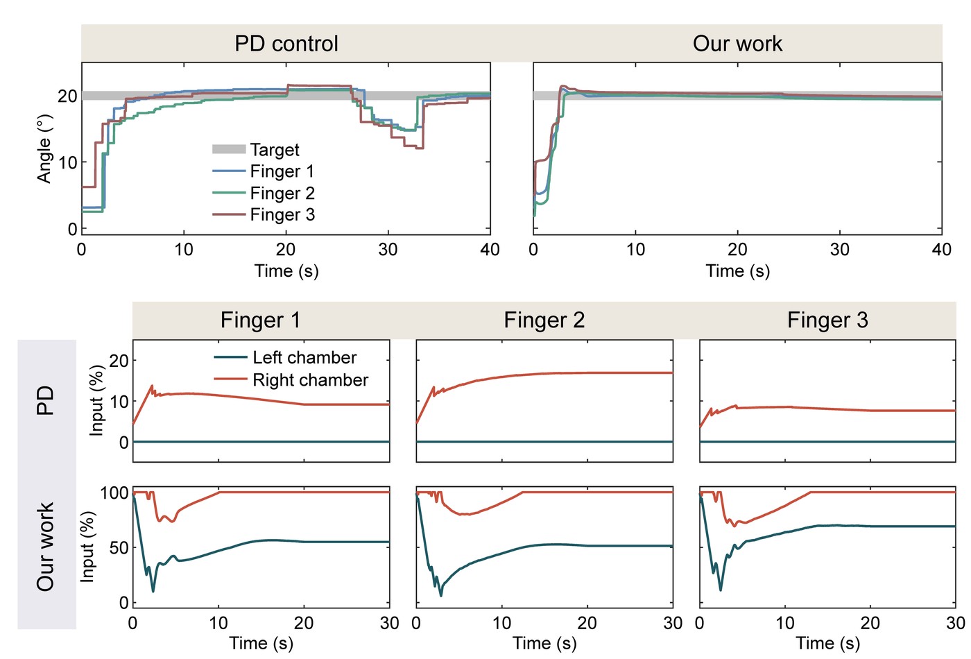
In the experiments, a Raspberry Pi generates a pulse width modulated signal for each chamber, which a converter turns into the voltage that sets the chamber's proportional pressure valve; the duty cycle is proportional to the chamber's negative pressure. The controller works with the duty cycles directly, so neither the pressure nor the valve needs a model. The robot followed a three-stage path of steps, at low, high and medium deflection, under four controllers: the stiffness-driven one, proportional-derivative (PD) control, Koopman-based MPC without the stiffness term (K-MPC), and reinforcement learning (RL). Over the whole path, the stiffness-driven controller tracked with an average error of 1.58°, against 2.37° for PD control, 3.21° for K-MPC and 5.25° for RL.
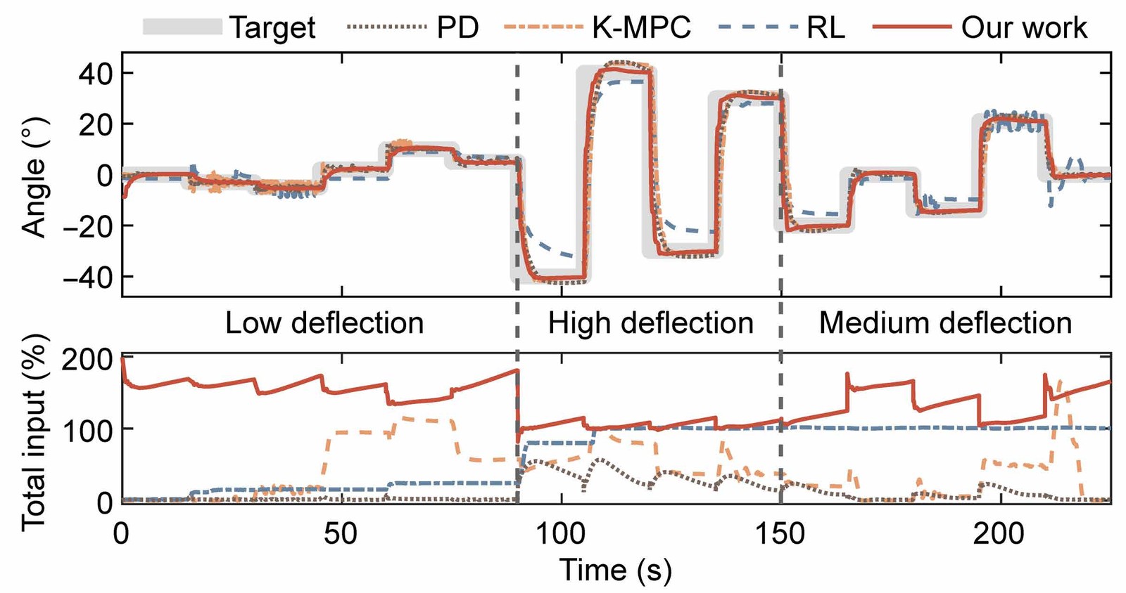
The gains come from stiffness. At low deflection, the three stiffness-free controllers chatter around their targets, with average angular velocities of 2.09°/s for PD control, 3.45°/s for K-MPC and 1.44°/s for RL, while the stiffness-driven controller moves at 0.43°/s; its input sum averages 157.22%, against 1.41%, 15.52% and 45.45%. PD control actuates only one chamber at a time. At high deflection, the stiffness-driven controller's tracking error is 2.96° (PD 5.83°, K-MPC 7.61°, RL 10.82°), and it reaches a band of ±1° around each target in 2.09 s on average (PD 3.67 s, K-MPC 3.25 s, RL 12.40 s). The RL baseline is a policy trained offline in a neural network model of the robot, fitted to the same data; the supplementary materials describe it as a conservative comparison rather than the best that reinforcement learning could do.
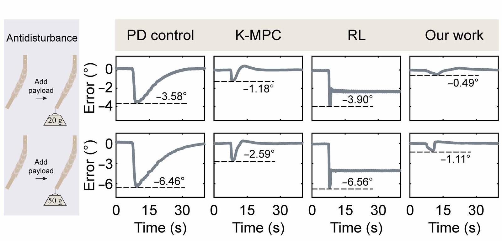
Holding 20° while a 20 g or 50 g weight is attached to its tip, the stiffness-driven controller deviates least: by at most 0.49° and 1.11°, against 3.58° and 6.46° for PD control, 1.18° and 2.59° for K-MPC, and 3.90° and 6.56° for RL. Its feedback and online reoptimization correct the deviation the load causes, while the high input sum, kept before and after the load is added, makes the robot resist it. Feedback partly corrects the deviation of the stiffness-free controllers too, but all three show clear offsets after the weight is added, and RL keeps its offset, because its policy was trained in a model identified without loads.
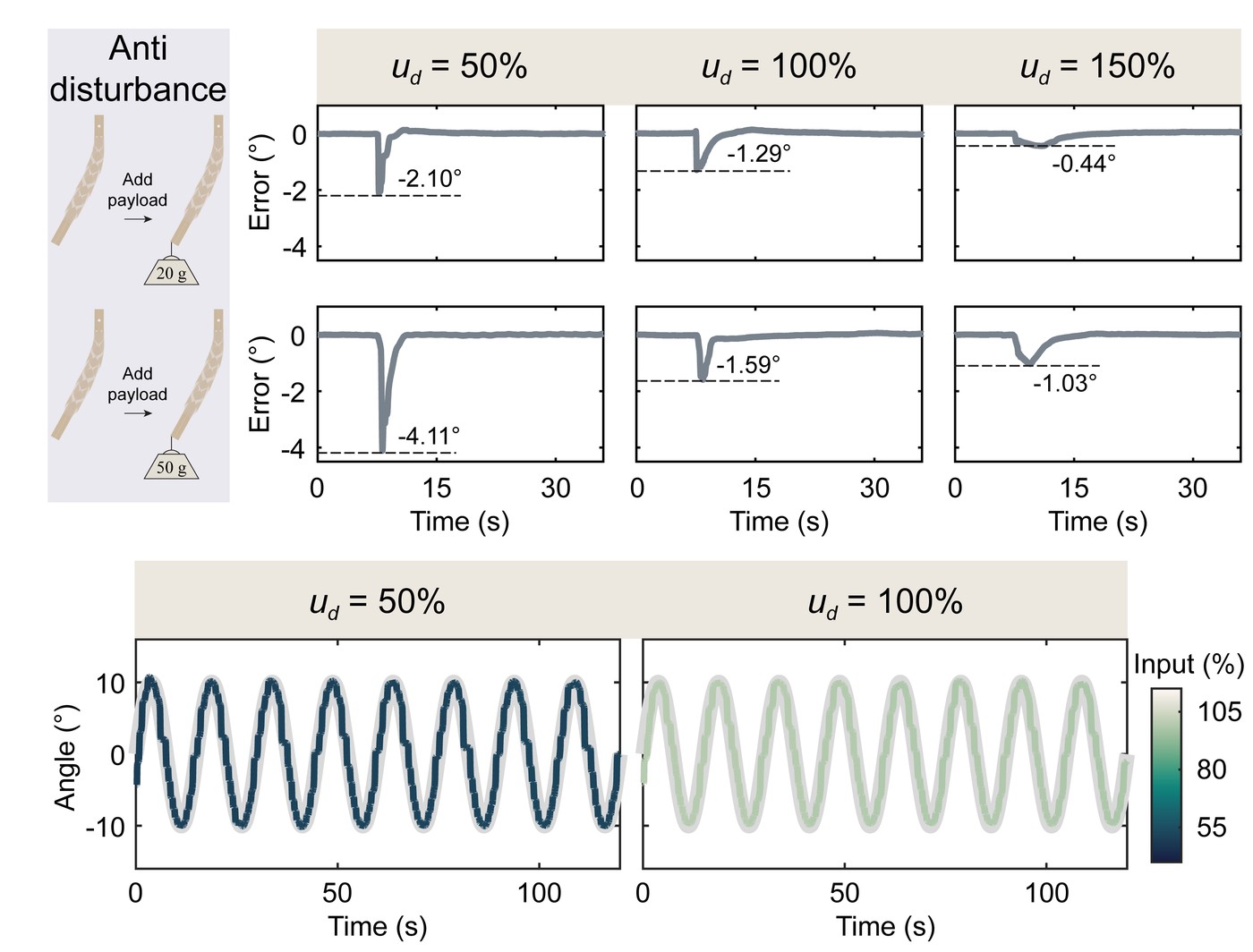
The input sum can also be given a target value, which sets the stiffness level. In tests at desired input sums of 50%, 100% and 150%, the largest error under either weight shrinks as the input sum rises, and the robot follows a sinusoidal path at fixed input sums of 50% and 100%.
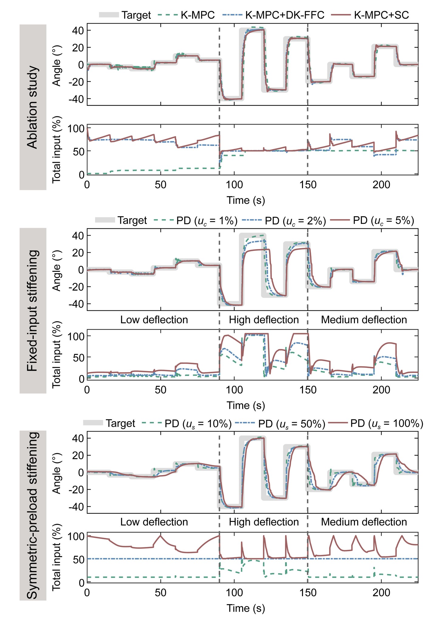
An ablation study separates the two additions. The stiffness constraint alone cuts K-MPC's tracking error from 3.21° to 1.94°, its largest error under the 50 g weight from 2.59° to 1.13° and its angular velocity at low deflection from 3.45 to 0.43°/s, but slows its response from 3.25 to 4.98 s. The feedforward compensator alone improves tracking (1.68°) and speeds the response to 2.80 s, but resists the weight less well than the stiffness constraint does (2.12°). Together they give 1.58°, 1.11°, 0.43°/s and 2.09 s. Stiffening PD control by hand helps only up to a point. A small fixed input on the opposing chamber, or a moderate symmetric preload on both, improves tracking and reduces vibration and the error under load, at the cost of a slower response; larger ones reduce vibration further but degrade tracking and slow the response more. A 100% symmetric preload, for example, resists the weight almost as well as the stiffness-driven controller (1.15° against 1.11°) but tracks with a 6.04° error and responds in 7.05 s.
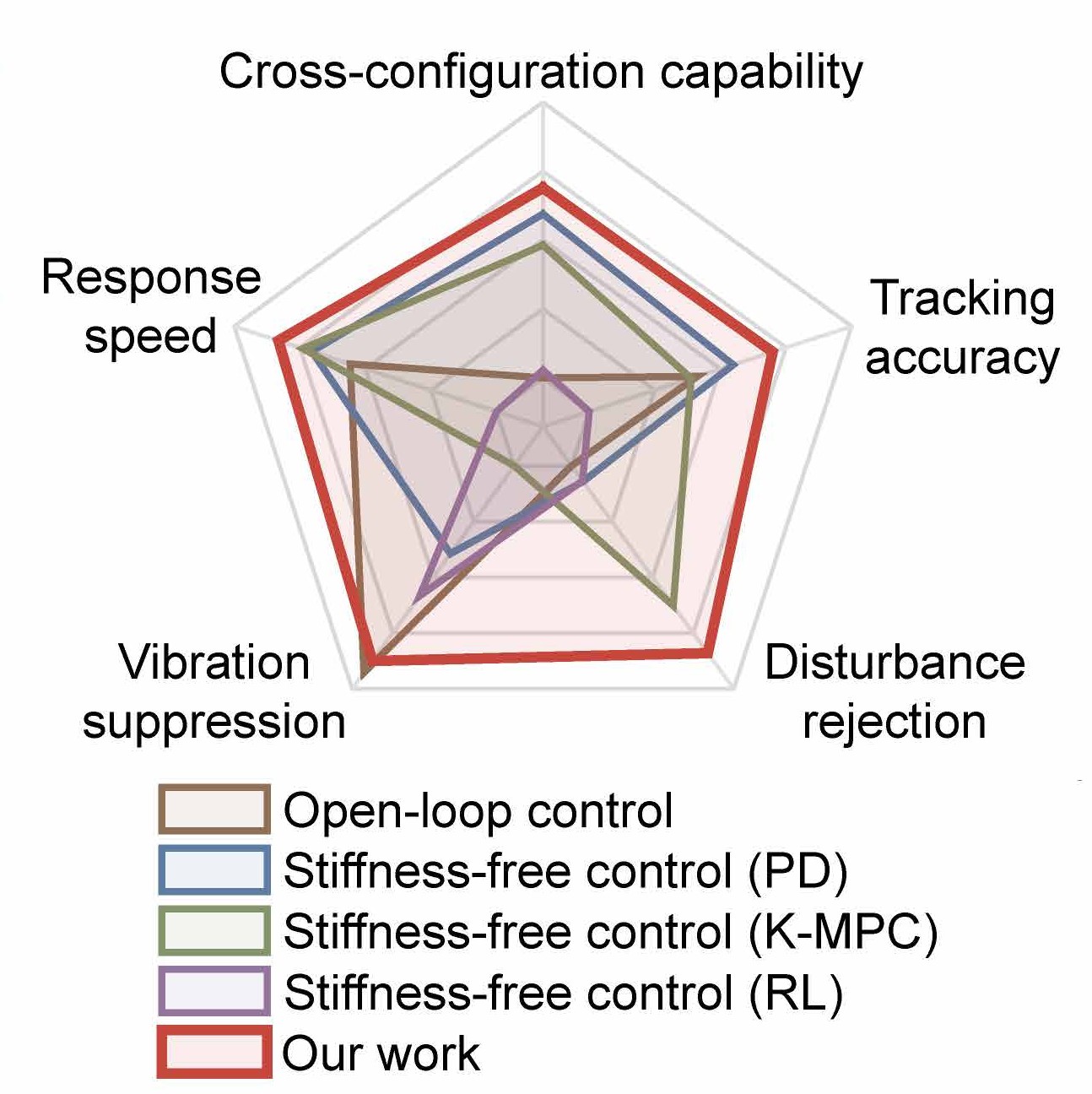
Across five measures, the stiffness-driven controller gives the best balance of the controllers compared. One measure comes from a preliminary test in which a model identified on one robot was applied unchanged to the pump and bridge robots of the applications below, which have different dimensions; the paper still recommends identifying each robot from its own data, which takes only minutes.
4 A three-finger gripper #
Three robots, spaced 120° apart on a round mount, make the fingers of a gripper. A power grip tests stiffness most directly: it holds an object by the stiffness of the fingers rather than by squeezing it. Each finger was bent to 20° without touching a rigid 67 g object, and the gripper was then lifted at 20 s, with no further change of input. Under PD control the fingers slid off the object; under stiffness-driven control the gripper lifted it.
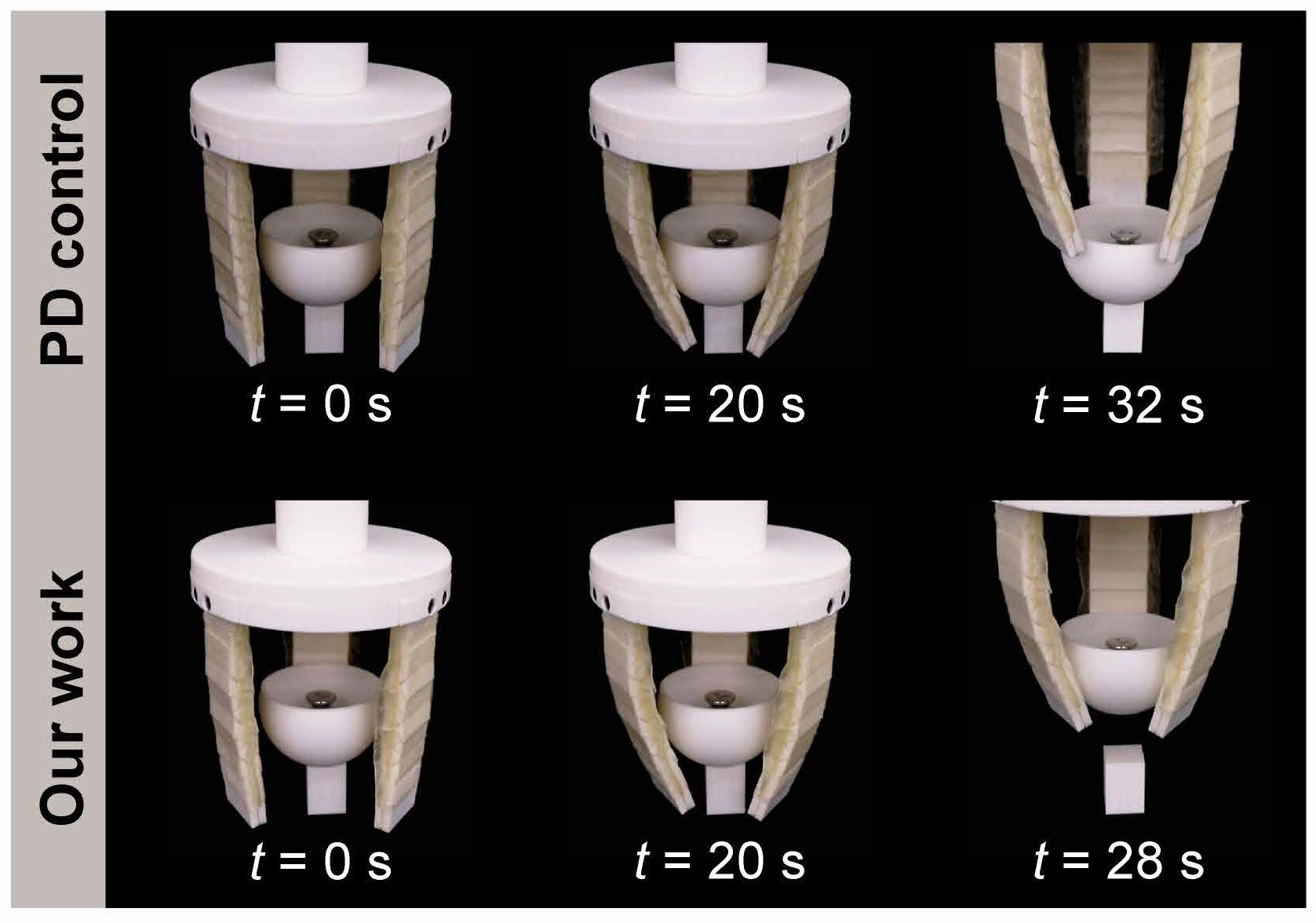
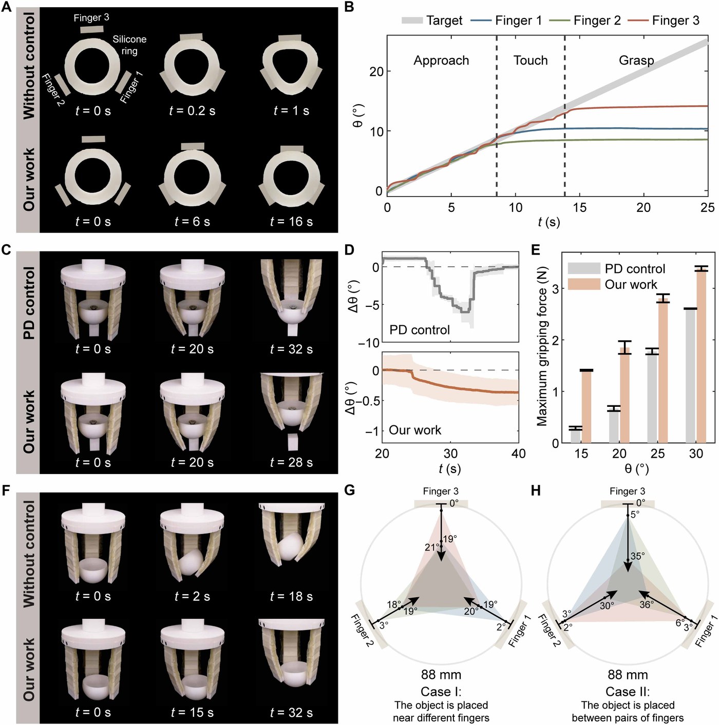
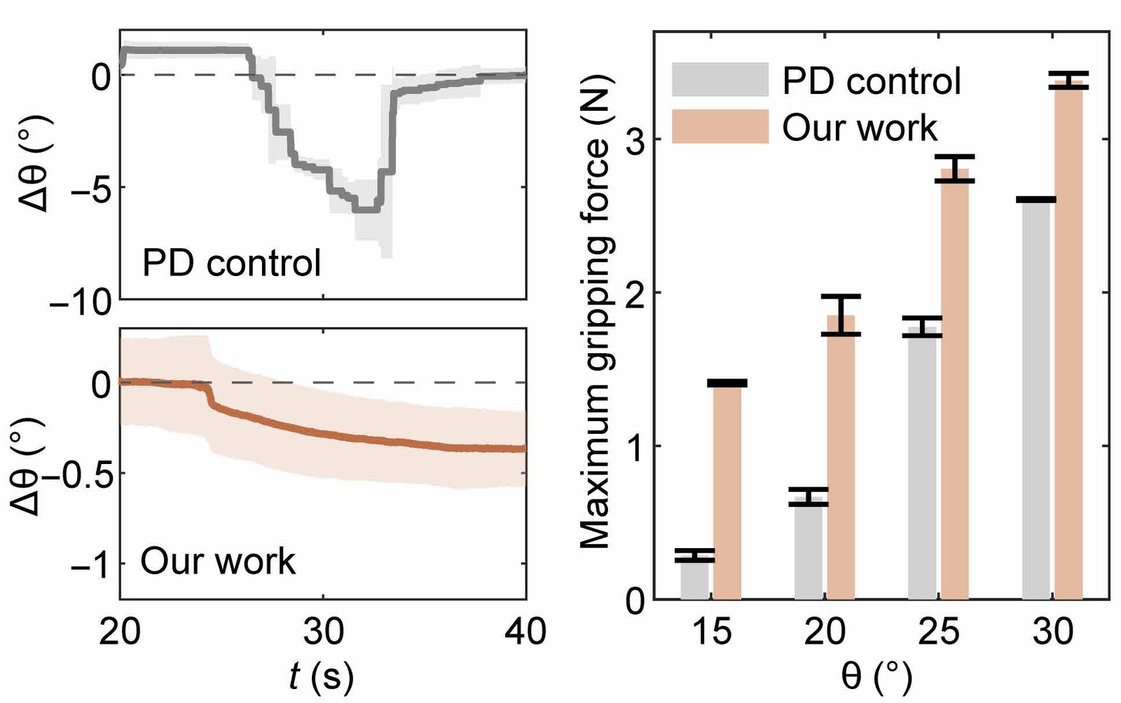
The stiffness-driven controller used inputs 17, 9 and 22 times higher than PD control in the three fingers; they differ because each finger's layered structure was assembled by hand. In tests on a universal testing machine (Mark-10), with the object fixed to the ground and the fingers bent to 15°, 20°, 25° or 30° before the gripper tried to lift it, the maximum gripping force rose by 391%, 177%, 58% and 30% over PD control.
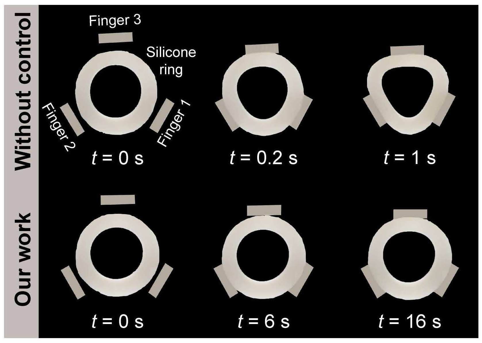
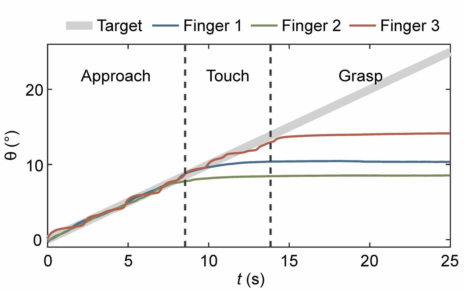
Pinching a soft silicone ring calls for precise control of the fingers instead. Direct actuation, simply depressurizing one chamber of each finger, squeezed the ring out of shape within a second. The stiffness-driven controller closed the fingers along a slowly rising target angle, and each finger stopped where it met the ring, through phases of approach, touch and grasp; the grasp phase begins once all three fingers touch. The ring was barely deformed.
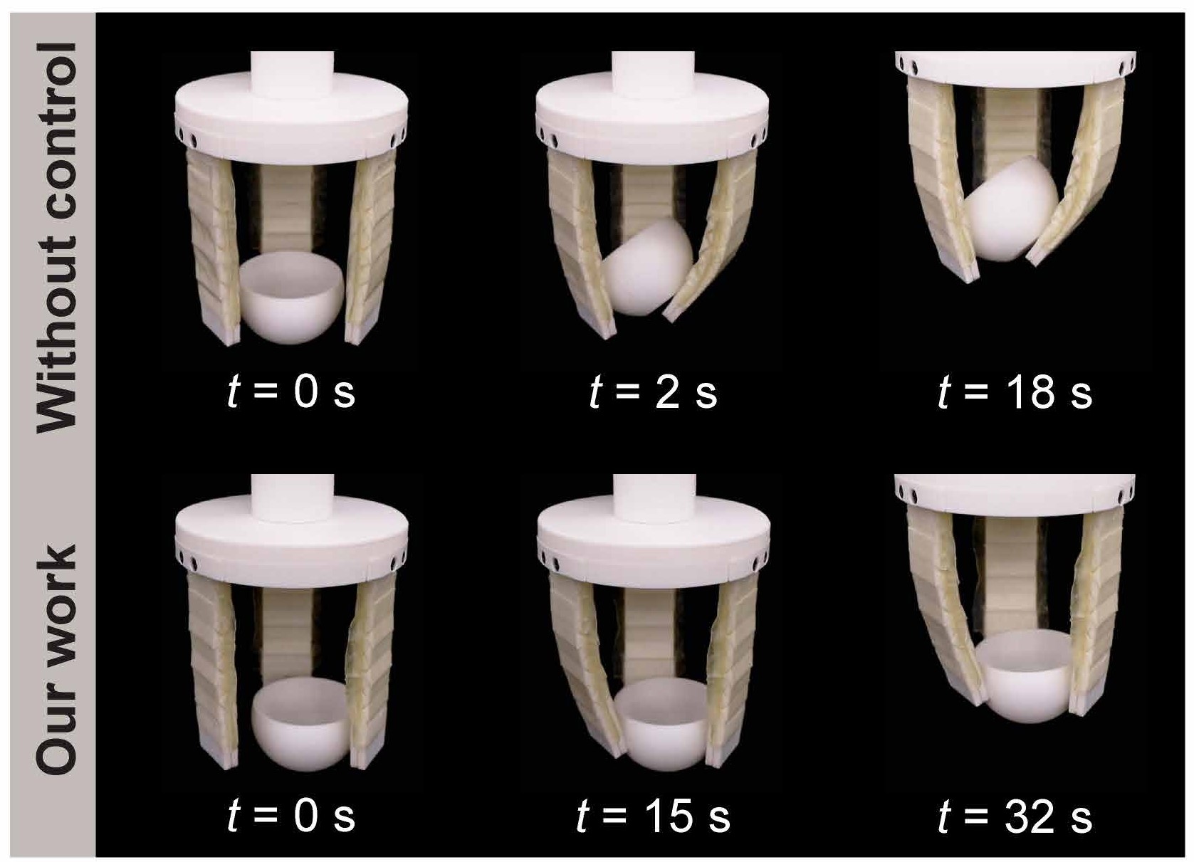
Light, delicate objects tip over easily when the fingers push unevenly. Direct actuation lifted a 17 g cup-shaped object, 64 mm across, but tilted it; the stiffness-driven controller lifted it level, even when it was placed at the edge of the gripper's reach, near one finger or between two.
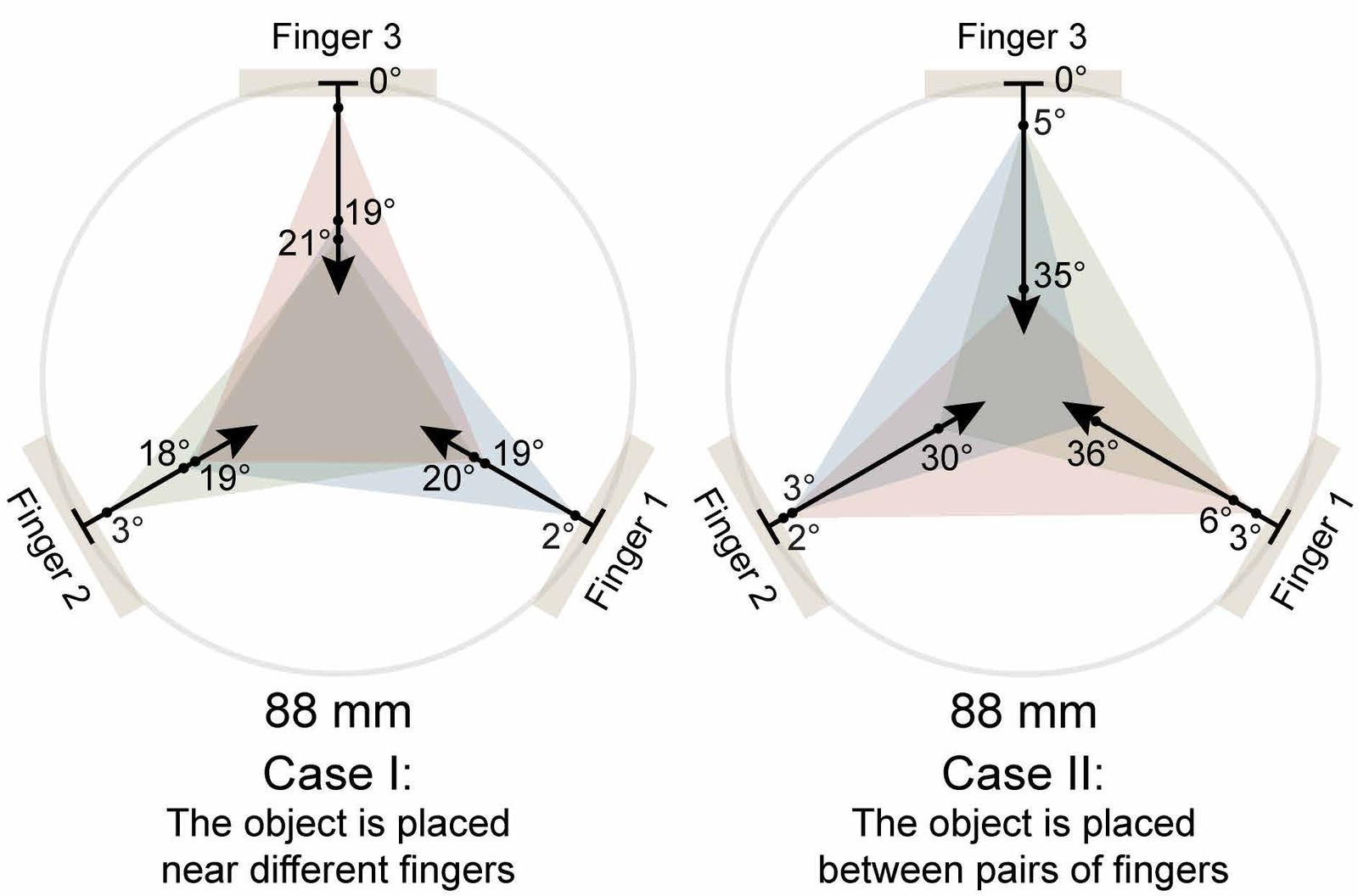
With the same controller, the gripper picks up soft objects such as a sponge and a cake, stiffer ones such as an apple and a ping pong ball, smooth ones that slip easily such as a glass cup and two beakers, and hollow ones such as a transparent box and a PLA sculpture, which it hooks from the inside. For a large toolbox, it first spreads its fingers outward.
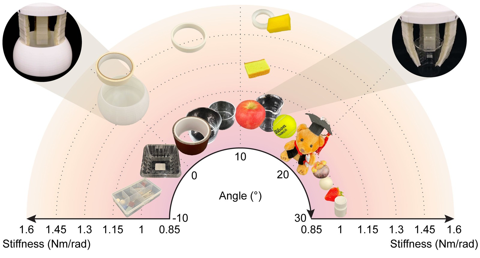
5 Stiffness sensing, a liquid pump and a bridge #
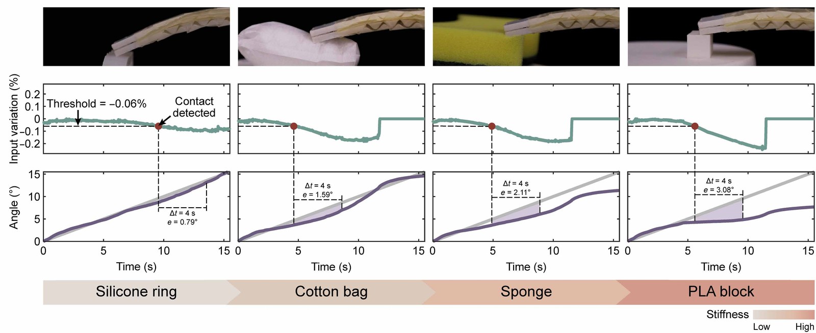
Because the controller keeps the robot on its path and notices contact, the robot can measure stiffness. Mounted horizontally, it follows a predefined path down onto an object; once the input variation signals contact, it keeps following the path, and the object resists according to its stiffness. The tracking error over the next 4 s ranks the objects from stiffest to softest: 3.08° for a PLA block, 2.11° for a sponge, 1.59° for a cotton bag and 0.79° for a silicone ring.
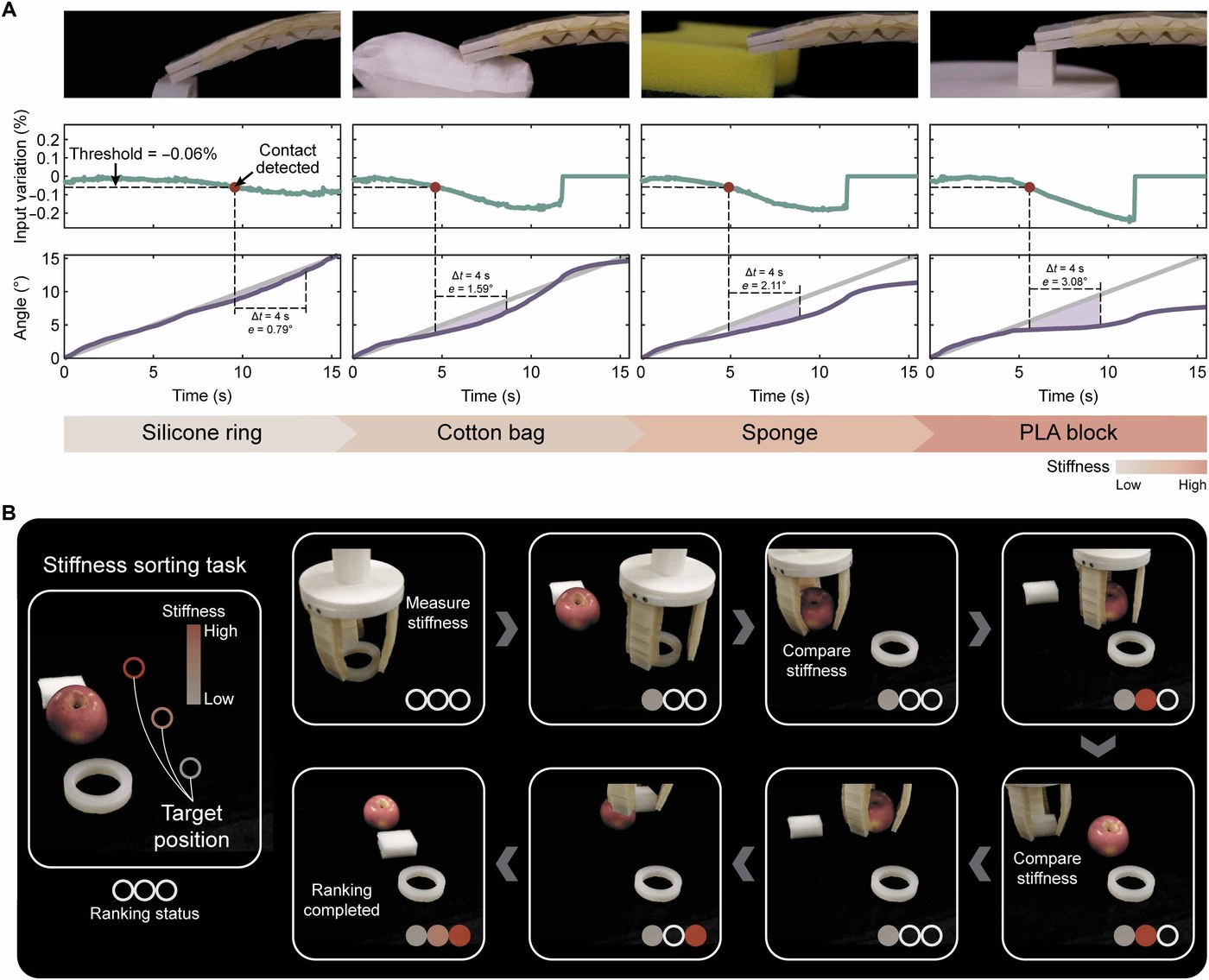
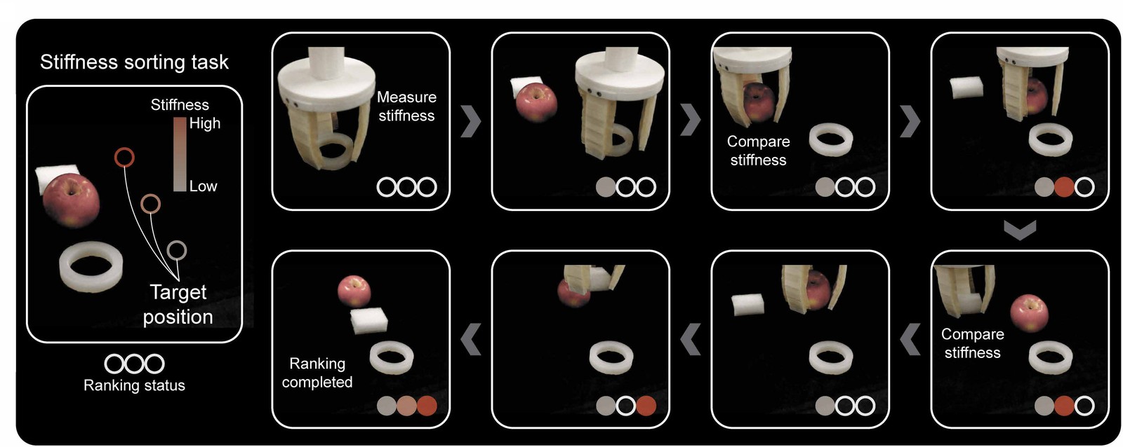
A three-finger gripper on a robot arm (Dobot CR3) used the same principle to sort objects while grasping them. It measured a silicone ring and placed it at the position for low stiffness, then found an apple stiffer and placed it at the intermediate position. An expanded polyethylene (EPE) foam block turned out to lie between the two, so the gripper moved the apple to the position for high stiffness and put the foam block in the middle. Over three trials, the tracking errors were 2.38 ± 0.07° for the ring, 2.66 ± 0.05° for the foam and 3.12 ± 0.01° for the apple.
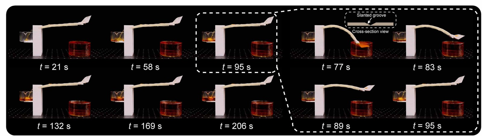
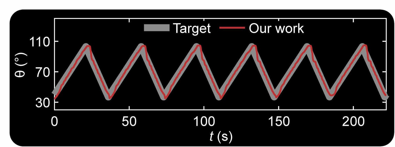
A robot twice as long as a gripper finger, with a slanted groove along its middle, works as a pump. In each cycle, it bends down to 37° to collect liquid from a lower container, then rises along a target path at 3°/s to 103°, which completes one transfer to a higher container, and returns at the same rate. Repeated, the cycles raise the liquid step by step, and the controller adjusts the collection angle to the current liquid level.
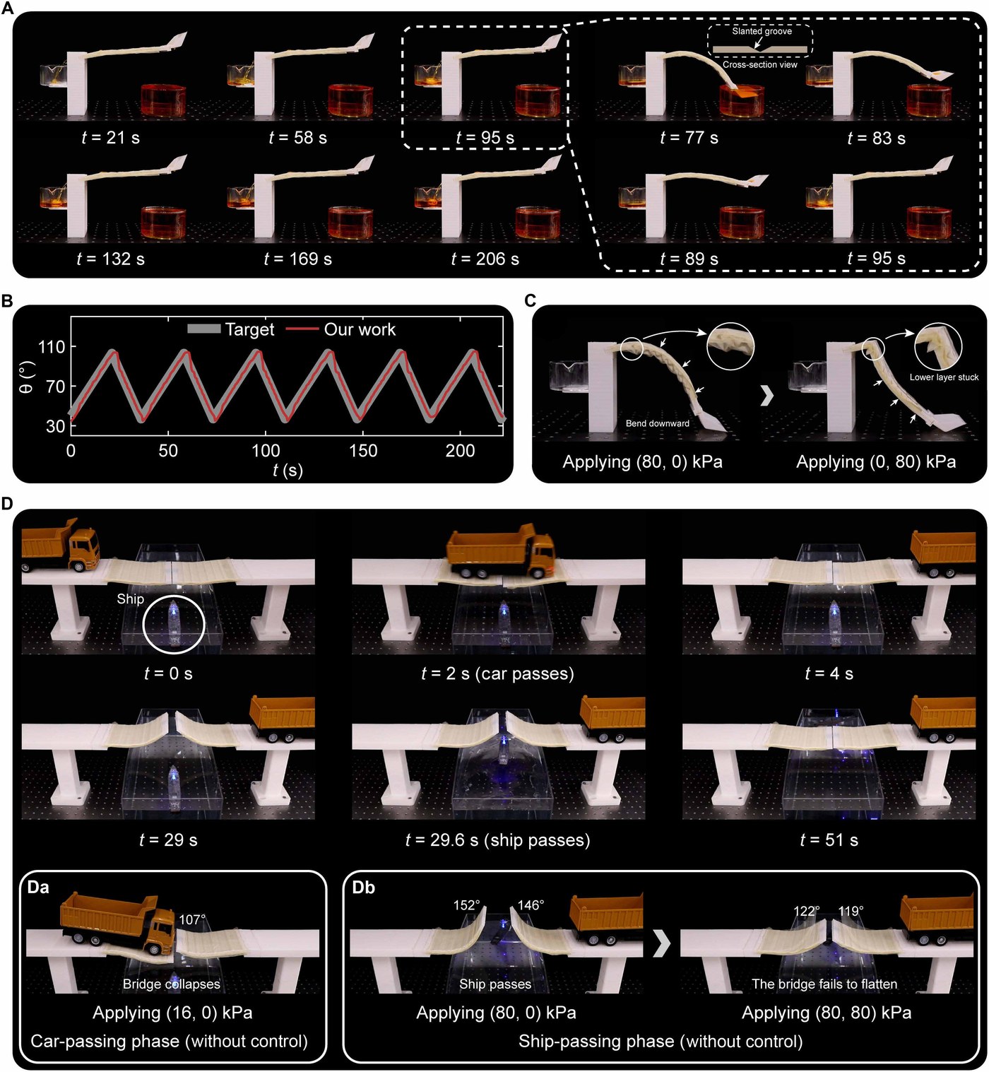
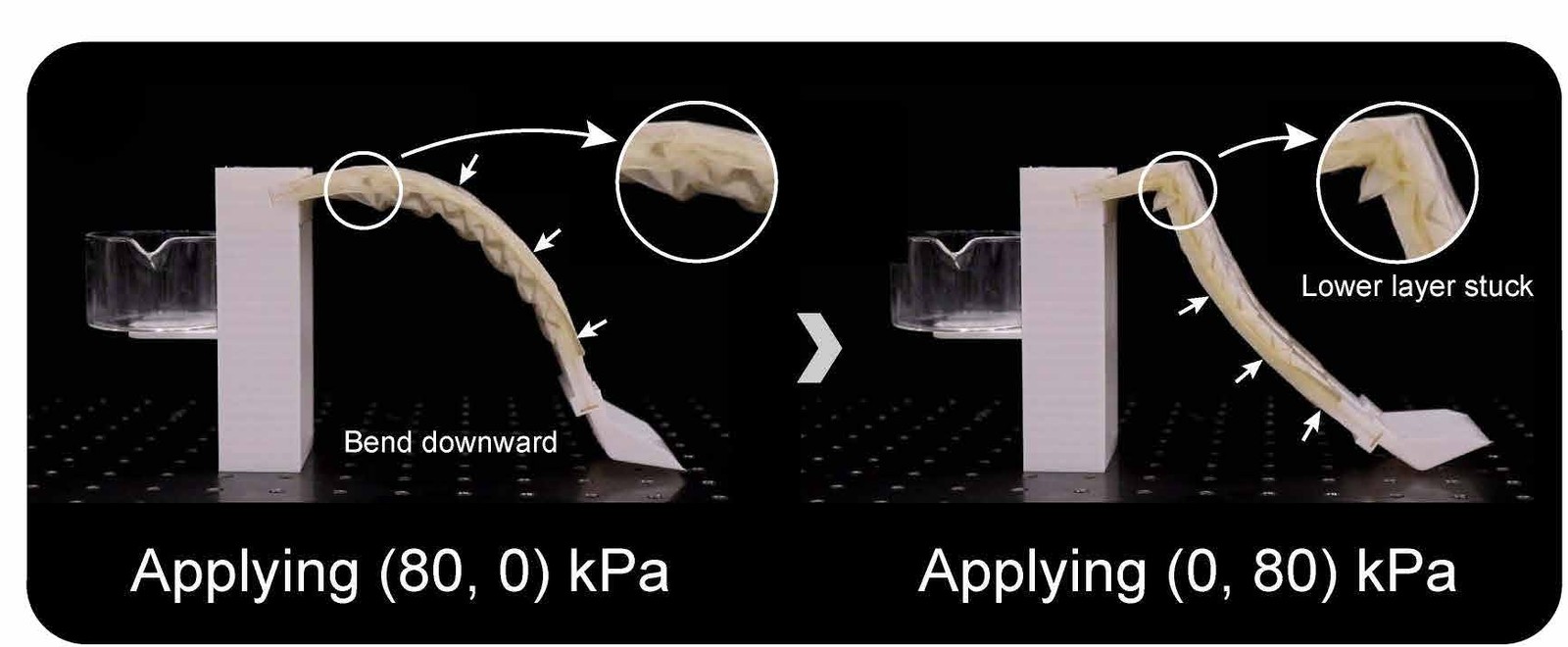
Without control, depressurizing the upper chamber bends the robot down, but the layered structure of the lower chamber can then stick under gravity, so that depressurizing the lower chamber no longer bends the robot back up.
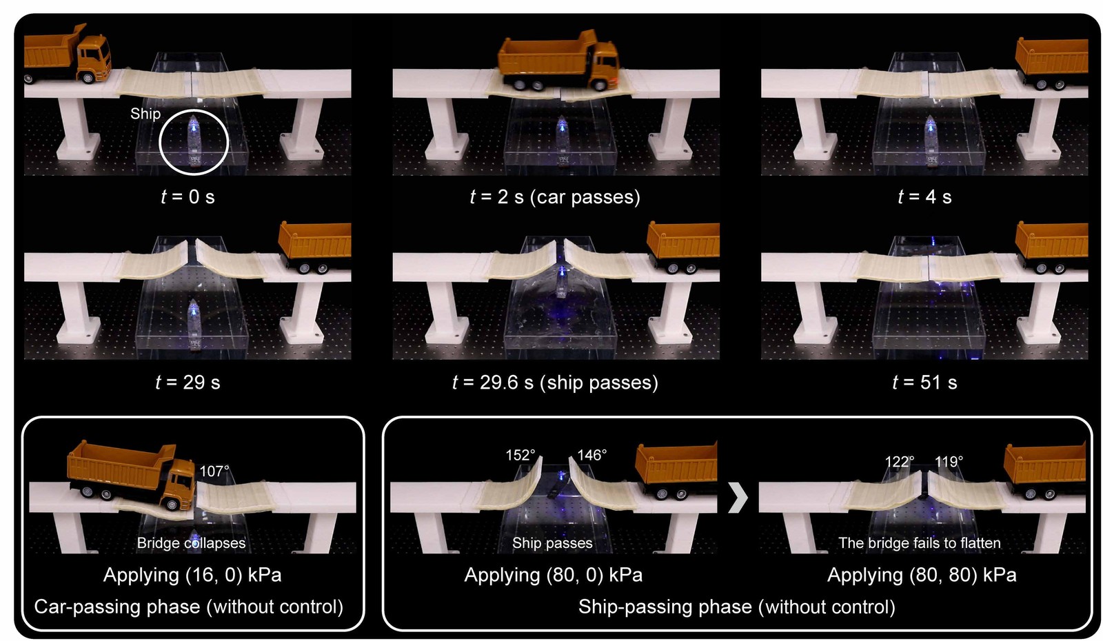
Two robots form the halves of a reconfigurable bridge, shown in the movie at the top of this page. To allow for gravity, the controller holds both halves at 95°, nearly flat, while a 410 g toy truck crosses, then raises them to 125° to let a ship pass beneath and lowers them again. Without control, 16 kPa in one chamber keeps the bridge nearly flat but too soft, and it sinks under the truck. With 80 kPa in one chamber alone, the halves rise to 146° and 152° for the ship, but bringing the opposite chamber to the same pressure returns them only to 119° and 122°, an impassable slope, although the same two pressures held the bridge flat before. The paper attributes this incomplete return to history-dependent behavior, likely due to friction between the scales and the base layer; the controller, which assumes no fixed relation between input and angle, corrects it with feedback.
6 A tendon-driven robot #
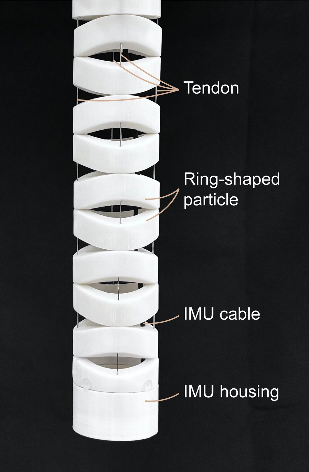
The strategy is not tied to pneumatic actuation. On a tendon-driven robot with two degrees of freedom, four antagonistic tendons, each pulled by its own motor, run through a column of ring-shaped particles, and an IMU at the tip measures yaw and pitch. Yaw and pitch share the tendons, so the robot is modeled as one coupled Koopman system, with the tendon tensions as first-order terms in the lifting function. Its stiffness depends mainly on the antagonistic force, the sum of the tensions in opposing tendons. A tension sensor on each tendon measures the tensions in real time, the controller's stiffness term is written in terms of them and a desired antagonistic force, and the sensors also guard against the sharp rise in tension that small motor commands can cause.
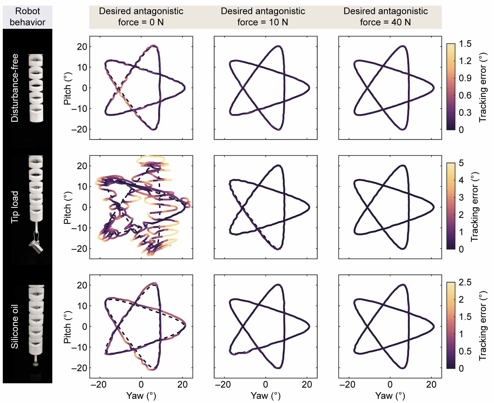
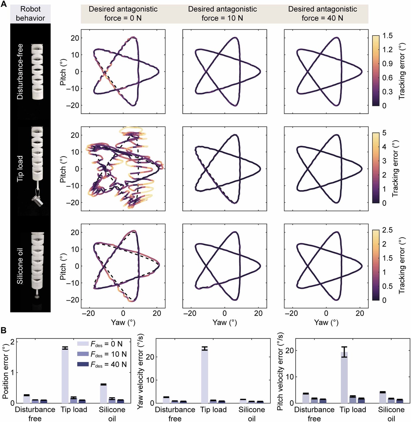
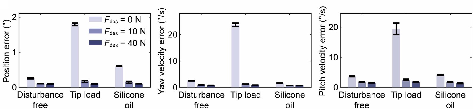
The robot traced a five-pointed star in yaw and pitch at desired antagonistic forces of 0, 10 and 40 N, with no disturbance, with a 100 g load at the tip, or with the tip immersed in silicone oil of 100,000 cSt, three times each, at a control interval of 30 ms. Without disturbance, raising the force from 0 to 10 N cut the position error from 0.260° to 0.107°, and 40 N added little (0.100°). With the tip load, the robot lost the star at 0 N (1.799°) and degraded at 10 N (0.176°), but held it at 40 N (0.101°). In the oil, viscous damping reduced the velocity errors in every configuration, yet the position error at 0 and 10 N grew (0.610° and 0.147°), while 40 N stayed precise (0.106°). Moderate stiffness may suffice under light conditions, but strong disturbances call for high stiffness.
The paper also states the method's limits. Learned from finite data, the model may not follow slow changes of the robot, such as material aging and wear, which online learning could address. And stiffness is regulated indirectly, through the actuation inputs and the robot's response, rather than measured in real time; pressure and visual sensing could make it explicit.
Movies #
The paper’s movies in full.
BibTeX #
@article{pan2026muscle,
  title = {Muscle coactivation-inspired stiffness-driven control strategy for antagonistic soft robots},
  author = {Pan, Jie and Chen, Tianyu and Li, Junwei and Wang, Yifan},
  journal = {Science Advances},
  volume = {12},
  number = {36},
  pages = {eaeg3346},
  year = {2026},
  doi = {10.1126/sciadv.aeg3346}
}